
Large-aperture large-field-of-view telescope system built-in measurement device and measurement method thereof

A measuring device and a technology with a large field of view, applied in the field of telescopes, can solve the problems of inability to adapt to high dynamic environmental changes, limitations of active optical telescope performance, inability to take into account large dynamic range and high positioning accuracy at the same time, etc., to achieve real-time Calibration and correction, improving the in-position time, and realizing the effect of positioning

Active Publication Date: 2020-10-16
CHANGCHUN INST OF OPTICS FINE MECHANICS & PHYSICS CHINESE ACAD OF SCI
View PDF27 Cites 7 Cited by
  • Summary
  • Abstract
  • Description
  • Claims
  • Application Information

AI Technical Summary

Problems solved by technology

However, the error sources that actually affect the telescope may change over time. Regular repeated calibration has high frequency selectivity and cannot adapt to highly dynamic environmental changes, which limits the further improvement of the performance of active optical telescopes.
At present, there are different technologies, none of which can take into account the large dynamic range and high positioning accuracy at the same time

Method used


Image

  • Large-aperture large-field-of-view telescope system built-in measurement device and measurement method thereof
  • Large-aperture large-field-of-view telescope system built-in measurement device and measurement method thereof
  • Large-aperture large-field-of-view telescope system built-in measurement device and measurement method thereof

Examples


Embodiment Construction

[0033] The following will clearly and completely describe the technical solutions in the embodiments of the present invention with reference to the accompanying drawings in the embodiments of the present invention. Obviously, the described embodiments are only some, not all, embodiments of the present invention. Based on the embodiments of the present invention, all other embodiments obtained by persons of ordinary skill in the art without making creative efforts belong to the protection scope of the present invention.

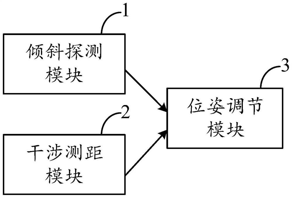
[0034] The invention provides a built-in measurement device for a large-aperture large-field telescope system, such as figure 1 shown, including:

[0035] The tilt detection module 1 is used to generate and image a plurality of laser beams, align the formed images, obtain the angle information of the wavefront through the offset of the light spot, and feed it back to the pose adjustment module 3;

[0036] The interference ranging module 2 is located on one si...


PUM


Abstract

The invention discloses a large-aperture large-field-of-view telescope system built-in measurement device and a measurement method thereof, and the device comprises an inclination detection module which is used for generating and imaging a plurality of laser beams, carrying out the alignment of the formed image, obtaining the wavefront angle information through the deviation of a light spot, and feeding back the wavefront angle information to a pose adjustment module; an interference distance measurement module, located on one side of the inclination detection module and used for measuring distance information of the optical truss and feeding back the distance information to the pose adjustment module; and a pose adjusting module used for driving the executing mechanism to adjust the spatial pose of the optical element according to the received angle information and distance information. An information source of the optical truss is formed by results obtained by angle measurement and distance measurement. The displacement and attitude between optical elements can be effectively monitored, so that continuous correction commands are provided for the system under the condition that the telescope cannot perform wavefront sensing through a guide star, real-time calibration and correction are realized in the operation process of the telescope, and the in-place time of the telescope is greatly prolonged.

Description

technical field [0001] The invention relates to the technical field of telescopes, in particular to a built-in measurement device and a measurement method for a large-aperture large-field telescope system. Background technique [0002] Large aperture and large field of view telescopes have developed rapidly in recent decades. In order to obtain higher sky survey efficiency and light collection capabilities, their apertures and fields of view are constantly expanding. Active optics, as the key technology of large aperture and large field of view telescopes, has been widely used. Many large-aperture and large-field-of-view telescopes have been developed and successfully operated abroad, and the eight-meter-class LSST has been put into construction, while domestic research on large-field-of-view telescopes over two meters has not yet been carried out. In order to further develop the detection capability of the large-aperture and large-field telescope, the independent and real-...

Claims


Application Information

Patent Timeline
Patent Type & Authority Applications(China)
IPC IPC(8): G02B23/00G01D21/02G05D3/12
CPCG01D21/02G02B23/00G05D3/12
Inventor 安其昌吴小霞林旭东王建立陈涛李洪文于致远
Owner CHANGCHUN INST OF OPTICS FINE MECHANICS & PHYSICS CHINESE ACAD OF SCI
Learn More