
Road and bridge engineering drainage structure

A technology of bridge engineering and drainage structure, applied in the direction of bridges, bridge parts, bridge construction, etc., can solve the problems of low drainage efficiency of drainage structure, blockage of drainage structure, and water in bridge area.

Active Publication Date: 2020-10-20
广东昇华建设工程有限公司
View PDF9 Cites 0 Cited by
  • Summary
  • Abstract
  • Description
  • Claims
  • Application Information

AI Technical Summary

Problems solved by technology

[0003] Passing vehicles and pedestrians on the bridge will bring some garbage and discard it on the bridge. When the rain suddenly hits, the scattered garbage will cause blockage of the drainage structure; thus causing serious flooding on the bridge; and the existing drainage structure will be difficult for some heavy rains As a result, the diversion capacity is insufficient, causing serious water accumulation on the bridge deck, which further affects the passing pedestrians and vehicles on the upper side of the bridge deck; the existing drainage structure has low drainage efficiency. Reduced capacity; inability to adjust the angle of the lower drain

Method used


Image

  • Road and bridge engineering drainage structure
  • Road and bridge engineering drainage structure
  • Road and bridge engineering drainage structure

Examples


Embodiment Construction

[0022] Embodiments of the present invention will be described below with reference to the drawings. In the process, in order to ensure the clarity and convenience of illustration, we may exaggerate the width of the lines or the size of the constituent elements in the diagram.

[0023] In addition, the following terms are defined based on the functions in the present invention, and may be different according to the user's or operator's intention or practice. Therefore, these terms are defined based on the entire content of this specification.

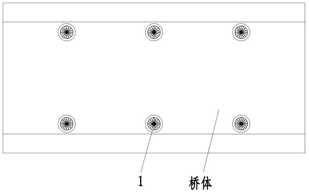
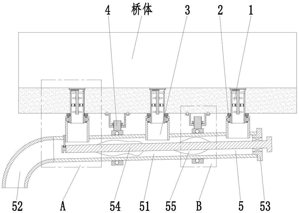
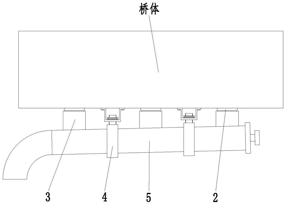
[0024] like Figure 1 to Figure 5 As shown, a road and bridge engineering drainage structure includes a socket unit 1, a rubber ring 2, a clamping unit 3, a fixing unit 4 and a flow guide unit 5; the socket unit 1 is evenly arranged on the bridge body. In the water hole, the evenly arranged sleeve units 1 are arranged in a straight line; the outer wall of the sleeve unit 1 located at the lower end of the bridge body is covered with a r...


PUM


Abstract

The invention provides a road and bridge engineering drainage structure. The road and bridge engineering drainage structure comprises a sleeving unit, a rubber ring, a clamping unit, a fixing unit anda flow guide unit. The road and bridge engineering drainage structure can solve the problems that passing vehicles and pedestrians on a bridge floor carry some garbage to be thrown on the bridge floor, and the scattered garbage can cause blockage of a drainage structure when rainwater suddenly comes; water accumulation of the bridge floor is serious; an existing drainage structure can cause insufficient flow guide capacity for some heavy rainstorms and the like, so that water is severely accumulated on the bridge floor, and pedestrians and vehicles passing through the upper end of the bridgefloor are further influenced; an existing drainage structure is low in drainage efficiency, and in order to gather water flow on the bridge floor, circulating water flow is gentle, and the water guidecapacity is reduced; and the angle of a lower-end drainage pipe cannot be adjusted.

Description

technical field [0001] The invention relates to the technical field of construction engineering, in particular to a road and bridge engineering drainage structure. Background technique [0002] In order to consider factors such as the anti-skid of the bridge deck when erecting road bridges, it is necessary to design a drainage structure on the bridge deck in order to ensure the safety of driving on the bridge deck. However, the current design of the bridge deck drainage structure still has the following problems: [0003] Passing vehicles and pedestrians on the bridge will bring some garbage and discard it on the bridge. When the rain suddenly hits, the scattered garbage will cause blockage of the drainage structure; thus causing serious flooding on the bridge; and the existing drainage structure will be difficult for some heavy rains As a result, the diversion capacity is insufficient, causing serious water accumulation on the bridge deck, which further affects the passing ...

Claims


Application Information

Patent Timeline
Patent Type & Authority Applications(China)
IPC IPC(8): E01D19/08
CPCE01D19/086
Inventor 沈靖林
Owner 广东昇华建设工程有限公司
Learn More