A light transmittance precision detection mechanism

A detection mechanism and light transmittance technology, applied in transmittance measurement, testing optical performance and other directions, can solve the problems of light leakage, affect the detection accuracy, and the flatness is difficult to fit tightly, and achieve the effect of improving stability and reducing light leakage.

Active Publication Date: 2020-11-24
SUZHOU DINNAR TECH FOR AUTOMATION CO LTD
View PDF6 Cites 0 Cited by
  • Summary
  • Abstract
  • Description
  • Claims
  • Application Information

AI Technical Summary

Problems solved by technology

In the prior art, the light source module is usually placed on the jig, and the product is placed on the light source module. The light-transmitting part of the product and the light-emitting part of the light source module face up and down. The light source module and the product are difficult to attach due to problems such as flatness. If it is tightly closed, it will cause light leakage, so that all the light emitted by the light-emitting part cannot enter the light guide hole, which will affect the detection accuracy.

Method used


Image

  • A light transmittance precision detection mechanism
  • A light transmittance precision detection mechanism
  • A light transmittance precision detection mechanism

Examples


Embodiment 1

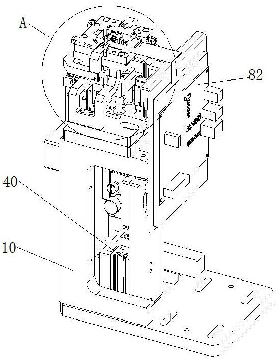
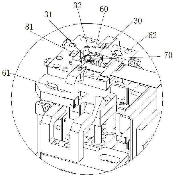
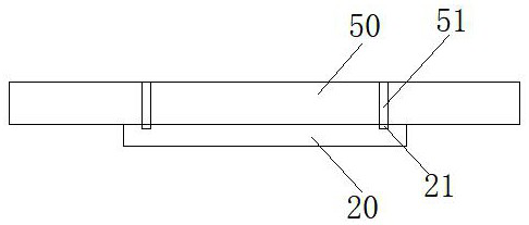
[0024] see Figure 1 to Figure 3 , as shown in the legend therein, a light transmittance precision detection mechanism includes a frame 10 and a detection system installed on the frame 10, the detection system includes a light source module 20 for emitting light, a light source module 20 for carrying The first jig 30 and the detection module used to detect the light transmittance, the first jig 30 is a floating jig, and the lower part of the first jig 30 is provided with a lifting drive device 40 for driving it up and down in the vertical direction, The outer periphery of the first jig 30 is provided with a second jig 60 for carrying the product 50 to be tested. The light source module 20 includes an upper surface and at least one light emitting portion 21 arranged on the upper surface. The product 50 to be tested includes a lower surface and a device. At least one light-transmitting portion 51 on the lower surface, when the product to be tested 50 and the light source module ...


PUM


Abstract

The invention discloses a precise detection mechanism for light transmittance, which includes a frame and a detection system, and the detection system includes a light source module for emitting light, a first jig for carrying the light source module, and a detection module for detecting light transmittance , the first jig is a floating jig, the bottom of the first jig is provided with a lifting drive device for driving it up and down in the vertical direction, and the outer periphery of the first jig is provided with a second jig for carrying the product to be tested. In the light transmittance precision detection mechanism disclosed in the present invention, after the product to be tested is placed, the light source module contacts the product to be tested during the rising process, and the light source module can self-adaptively adjust its own posture to promote the light transmission part of the product and the light source The light-emitting part of the module can be more closely bonded, reducing light leakage and improving the stability of the test.

Description

technical field [0001] The invention relates to the field of light transmittance detection, in particular to a precise light transmittance detection mechanism. Background technique [0002] Some products need to be equipped with a light-transmitting part. The light-emitting part of the light source module provides an incident light to the light-transmitting part and generates a transmitted light. The intensity of the transmitted light is sensed by a photoresistive sensor and an analog signal is generated. Through an AD conversion module The analog signal is converted into a digital signal, and the digital signal is processed by a single-chip computer to calculate the light transmittance (light transmittance) of the product to be tested. In the prior art, the light source module is usually placed on the jig, and the product is placed on the light source module. The light-transmitting part of the product and the light-emitting part of the light source module face up and down. ...

Claims


Application Information

Patent Timeline
Patent Type & Authority Patents(China)
IPC IPC(8): G01N21/59G01M11/02
CPCG01M11/02G01N21/59
Inventor 秦应化姚亮亮杜义祥
Owner SUZHOU DINNAR TECH FOR AUTOMATION CO LTD
Why Eureka
Try Eureka