
A three field of view switching mechanism for optical equipment

A technology of switching mechanism and optical equipment, applied in the directions of optics, optical components, installation, etc., can solve the problem that the positioning accuracy and repeated positioning accuracy cannot meet the requirements of use

Active Publication Date: 2020-10-20
XI'AN INST OF OPTICS & FINE MECHANICS - CHINESE ACAD OF SCI
View PDF7 Cites 3 Cited by
  • Summary
  • Abstract
  • Description
  • Claims
  • Application Information

AI Technical Summary

Problems solved by technology

[0006] The purpose of the present invention is to provide a three-view field switching mechanism for optical equipment, so as to solve the problem that the existing field of view switching mechanism cannot meet the use requirements in terms of positioning accuracy and repeat positioning accuracy under the condition of visible light television equipment and harsh environments technical problem

Method used


Image

  • A three field of view switching mechanism for optical equipment
  • A three field of view switching mechanism for optical equipment
  • A three field of view switching mechanism for optical equipment

Examples


Embodiment Construction

[0064] The present invention will be described in detail below in conjunction with the accompanying drawings and specific embodiments.

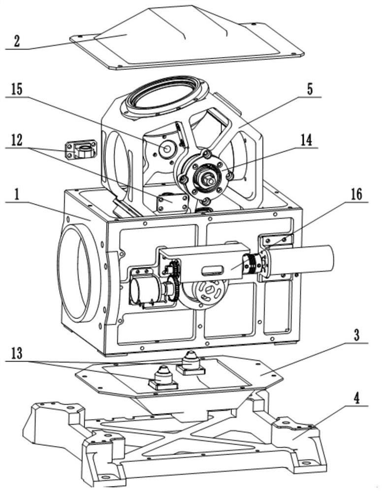
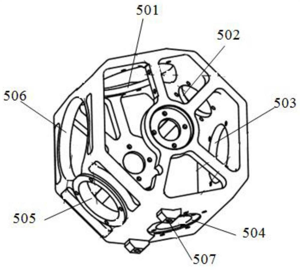
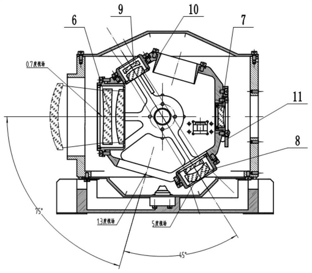
[0065] see figure 1 , the present invention is a three-field switching mechanism for optical equipment, including a main frame assembly, a rotating lens barrel assembly, a driving assembly 16 and a limit assembly.

[0066] The above-mentioned main frame assembly includes the main frame 1 . In this embodiment, for the sake of simple processing and cost saving, the main frame 1 preferably adopts a box structure, which is a rectangular frame, and its upper and lower sides are opened to facilitate the installation of the rotating lens barrel 5 . The main frame assembly in this embodiment also includes an upper cover plate 2 and a lower cover plate 3; the upper cover plate 2 and the lower cover plate 3 are respectively covered on the upper and lower surfaces of the main frame 1, are fixedly connected with the main frame 1, and surround into a ca...


PUM


Abstract

The invention relates to a field-of-view switching mechanism for optical equipment, in particular to a three-field-of-view switching mechanism for optical equipment, and solves the problem that the positioning and repeated positioning precision of an existing switching mechanism cannot meet the use requirements under the condition of visible light television equipment and in a severe environment.The switching mechanism is characterized by comprising a main frame assembly, a rotating lens barrel assembly and a limiting assembly which are arranged in a main frame, and a driving assembly; the rotating lens barrel assembly comprises a rotating lens barrel, a first switching lens group, a fourth switching lens group, a light shield, a second switching lens group, a third switching lens group,a first inner shaft and a second inner shaft, wherein the first switching lens group, the fourth switching lens group, the light shield, the second switching lens group and the third switching lens group are sequentially installed on the circumferential side face of the rotating lens barrel clockwise, and the first inner shaft and the second inner shaft are fixedly connected to the two ends of therotating lens barrel respectively and rotationally connected with the main frame; a light through hole is formed in the circumferential side surface of the rotary lens barrel; the first switching lens group and the second switching lens group, the fourth switching lens group and the third switching lens group, and the light shield and the light through hole are separately coaxial; the limiting assembly comprises two magnet limiting assemblies and a plunger limiting assembly.

Description

technical field [0001] The invention relates to a visual field switching mechanism for optical equipment, in particular to a three visual field switching mechanism for optical equipment. Background technique [0002] The ship-borne photoelectric theodolite is mainly used for real-time tracking and measurement of fast targets, and the visible light TV measurement system is an important part of it. With the diversification of work task requirements, the visible light imaging system is required to have a multi-field of view switching function, so that it can detect longer-distance targets in the long-focus small field of view, and at the same time conduct a large-scale search in the short-focus large field of view, so as to realize Accurate tracking and capture of targets. [0003] The switching of the field of view is to control the movement of the corresponding lens group of the optical system to cause the change of the focal length, thereby realizing the change of the field...

Claims


Application Information

Patent Timeline
IPC IPC(8): G02B7/16G02B7/02
CPCG02B7/021G02B7/16
Inventor 彭建伟陈卫宁史魁曲锐闫强赵岳岳娟
Owner XI'AN INST OF OPTICS & FINE MECHANICS - CHINESE ACAD OF SCI
Learn More