

Intelligent energy management system
A smart energy and management system technology, applied in information technology support systems, data processing applications, instruments, etc., can solve problems such as unfavorable smart energy development and digital transformation, and loose smart energy management
- Summary
- Abstract
- Description
- Claims
- Application Information
AI Technical Summary
Problems solved by technology
Method used
Image

Examples
Embodiment 1
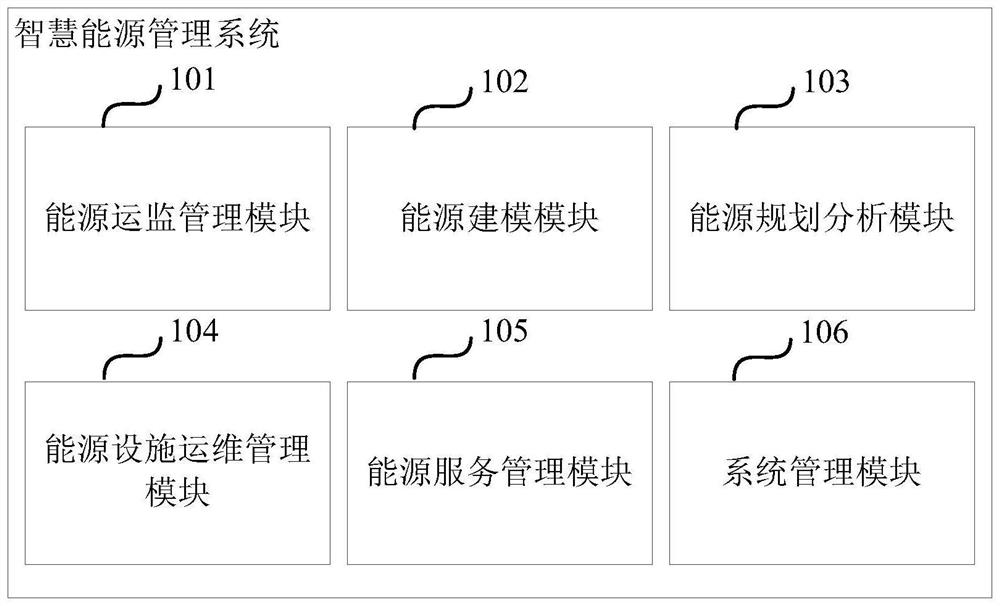
[0018] figure 1 It is a schematic structural diagram of a smart energy management system provided by Embodiment 1 of the present invention. This embodiment is applicable to the situation of unified management of the whole cycle of generation, transmission and consumption of smart energy.
[0019] Such as figure 1 As shown, the system in the embodiment of the present invention specifically includes: an energy operation monitoring management module 101, an energy modeling module 102, an energy planning analysis module 103, an energy facility operation and maintenance management module 104, an energy service management module 105, and a system management module 106.
[0020] The energy operation monitoring management module 101 is used to obtain the relevant data of each smart energy in the smart energy demonstration area, and perform statistical analysis on the relevant data of each smart energy; display the relevant data and statistical analysis results of each smart energy; ...
Embodiment 2
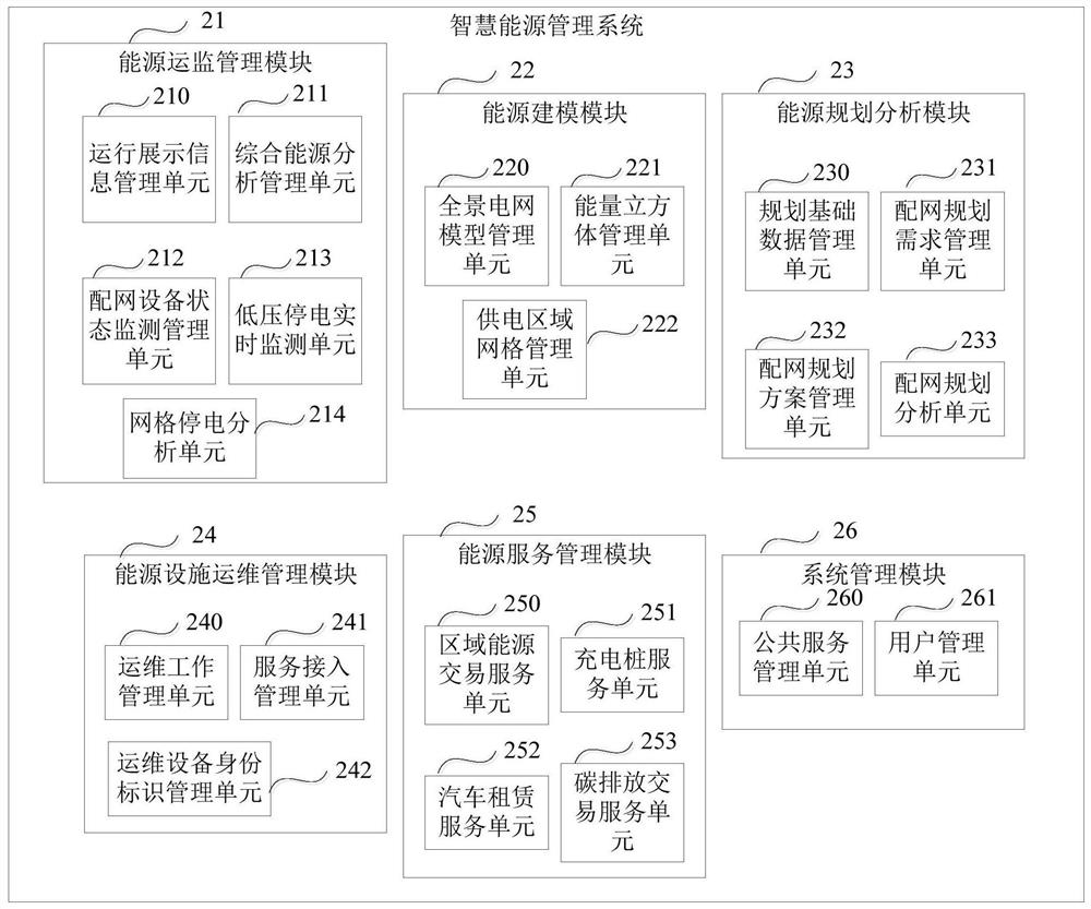
[0038] figure 2 It is a schematic structural diagram of a smart energy management system provided in Embodiment 2 of the present invention, as shown in figure 2 As shown, the system in the embodiment of the present invention specifically includes: an energy operation monitoring management module 21, an energy modeling module 22, an energy planning analysis module 23, an energy facility operation and maintenance management module 24, an energy service management module 25, and a system management module 26;
[0039] The energy operation monitoring management module 21 is used to obtain the relevant data of each smart energy in the smart energy demonstration area, and perform statistical analysis on the relevant data of each smart energy; display the relevant data and statistical analysis results of each smart energy;
[0040] The energy modeling module 22 is used to display each energy-related model in the smart energy demonstration area, and manage each energy-related model...
Embodiment 3
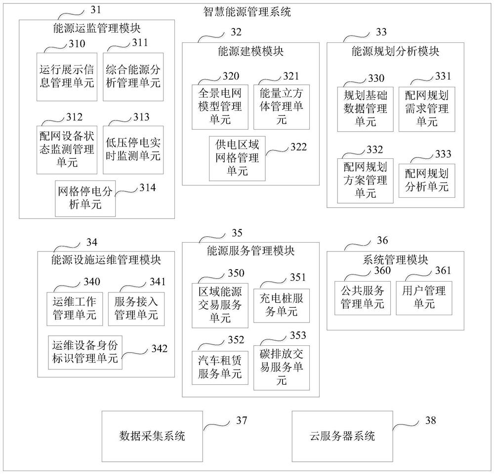
[0093] image 3 It is a schematic structural diagram of a smart energy management system provided in Embodiment 3 of the present invention, as shown in image 3 As shown, the system in the embodiment of the present invention specifically includes: an energy operation monitoring management module 31, an energy modeling module 32, an energy planning analysis module 33, an energy facility operation and maintenance management module 34, an energy service management module 35 and a system management module 36;
[0094] Among them, the energy operation monitoring management module 31 includes an operation display information management unit 310, a comprehensive energy analysis management unit 311, a distribution network equipment status monitoring management unit 312, a low-voltage power outage real-time monitoring unit 313, and a grid power outage analysis unit 314;
[0095] Wherein, the energy modeling module 32 includes a panoramic power grid model management unit 320, an energy...
PUM
 Abstract
Description
Claims
Application Information