
Front-back visual implementation method, device and system based on thermodetector

An implementation method and technology of a thermometer, which is applied in the field of thermometers, can solve the problems of being unable to observe the temperature change of the individual under test in real time, reducing the user's operation convenience and self-test experience, and poor use convenience.

Pending Publication Date: 2020-10-20
UNI TREND TECH (CHINA) CO LTD
View PDF0 Cites 0 Cited by
  • Summary
  • Abstract
  • Description
  • Claims
  • Application Information

AI Technical Summary

Problems solved by technology

At present, the traditional thermometer is only provided with a single display unit at its rear end, that is, a single rear-view type thermometer. This type of thermometer can only be used by the tester to observe the body temperature detection information during the temperature measurement process, and is used The individual at the measuring end cannot know the body temperature detection information, which is not convenient to use and cannot cover all usage scenarios well; another example is that when the user measures the forehead temperature by himself, he cannot observe the current body temperature detection information in a convenient and timely manner, and needs to use the temperature measurement In addition, in the process of self-testing temperature, it is impossible to observe and know the temperature changes of the individual under test at different angles and positions in real time. The operation is limited by the directionality, which greatly reduces the user's operation. Convenience and self-test experience

Method used


Image

  • Front-back visual implementation method, device and system based on thermodetector
  • Front-back visual implementation method, device and system based on thermodetector
  • Front-back visual implementation method, device and system based on thermodetector

Examples


Embodiment 1

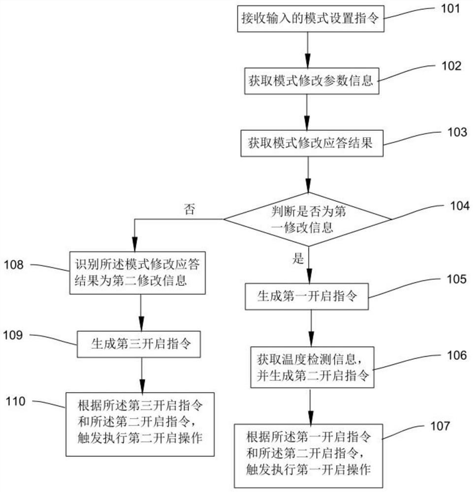
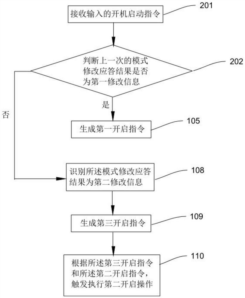
[0062] Embodiment 1: see figure 1 , this embodiment uses a conventional human body temperature measurement scene for further illustration. This embodiment discloses a front and rear visual realization method based on a thermometer, which is applied to a measuring device with a first display unit and a second display unit. Thermometer, described method comprises:

[0063] Step 101, receiving an input mode setting command, the mode setting command represents a setting command of a self-test mode or a non-self-test mode;

[0064] Step 102, acquiring mode modification parameter information according to the mode setting instruction;

[0065] Step 103, obtain a mode modification response result through the mode modification parameter information, and the mode modification response result represents the setting result of the user setting and inputting the self-test mode or the non-self-test mode;

[0066] Step 104, judging whether the mode modification response result is first modifi...

Embodiment 2

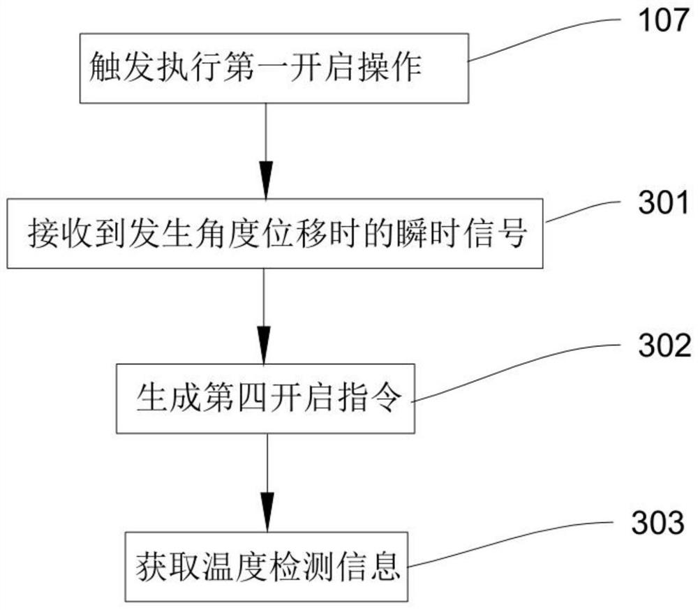
[0107] Example 2: see image 3 , this embodiment is an extension and improvement on the basis of Embodiment 1, that is, a front and rear visual realization method based on a thermometer disclosed in this embodiment also includes:

[0108] If step 107 is executed: after the first opening operation is triggered, dynamic temperature measurement monitoring is performed, that is, the thermometer enters the dynamic temperature measurement mode, so that the user can observe the temperature detection information at different angles and different positions in real time, so as to To make it easier and quicker to read the real-time temperature detection information of the individual under test, the method also includes:

[0109] Step 301, receiving an instantaneous signal when an angular displacement of the thermometer occurs;

[0110] Step 302, generating a fourth opening instruction according to the instantaneous signal;

[0111] Step 303, according to the fourth opening instruction,...

Embodiment 3

[0116] Embodiment 3: see Figure 5 , this embodiment is an extension and improvement on the basis of embodiment 2. Since the body temperature of the human body fluctuates depending on the ambient temperature, this embodiment uses the scene of measuring the body temperature of the human body when the ambient temperature is high or low For further explanation, that is, a thermometer-based front and rear visual realization method disclosed in this embodiment also includes:

[0117] After performing step 106: obtaining temperature detection information, and generating a second opening instruction according to the temperature detection information, the method further includes:

[0118] Step 401, judging whether the temperature detection information is greater than the warning temperature, the warning temperature can be set according to the actual detection needs, for example, the warning temperature in this embodiment is 37.3°C;

[0119] If not, then execute the step 107;

[0120...


PUM


Abstract

The invention discloses a front-back visual implementation method based on a thermodetector. The front-back visual implementation method is applied to a thermodetector provided with a first display unit and a second display unit and comprises the following steps: receiving an input mode setting instruction; acquiring mode modification parameter information; obtaining a mode modification response result; judging whether the mode modification response result is first modification information or not; if yes, generating a first starting instruction; obtaining temperature detection information, andgenerating a second starting instruction according to the temperature detection information; and triggering to execute first opening operation according to the first starting instruction and the second starting instruction. The invention further discloses a front-back visual implementation device and system based on the thermodetector. The second display unit is additionally arranged at the frontend of the thermodetector, the second display unit is selected to be turned on or turned off according to actual needs through the front-back visual implementation method, a user can independently set a self-test mode or a non-self-test mode, and therefore compared with a conventional rearview thermodetector, convenience and selectivity for reading temperature detection information in real time are improved.

Description

technical field [0001] The invention relates to the technical field of thermometers, in particular to a method, device and system for implementing front and rear visualization based on thermometers. Background technique [0002] With the continuous development of the technical level of the thermometer, and the thermometer has been more and more widely used in civil, industrial, medical, electric power and fire protection and other fields, the research and development of its operation convenience and feasibility has also attracted the attention of the world. countries' attention. At present, the traditional thermometer is only provided with a single display unit at its rear end, that is, a single rear-view type thermometer. This type of thermometer can only be used by the tester to observe the body temperature detection information during the temperature measurement process, and is used The individual at the measuring end cannot know the body temperature detection informatio...

Claims


Application Information

Patent Timeline
IPC IPC(8): G16H40/60G06F9/445G01K13/00
CPCG16H40/60G06F9/44505G01K13/00
Inventor 黄宏原杨志凌薛淦文
Owner UNI TREND TECH (CHINA) CO LTD
Learn More