Power-saving lithium battery box convenient to disassemble and assemble

A lithium battery, power-saving technology, applied in battery pack parts, circuits, electrical components, etc., can solve problems such as lithium battery leakage

Active Publication Date: 2020-10-20
厦门派客新能源科技有限公司
View PDF3 Cites 0 Cited by
  • Summary
  • Abstract
  • Description
  • Claims
  • Application Information

AI Technical Summary

Problems solved by technology

[0005] The purpose of the present invention is to solve the problem that most traditional lithium battery boxes are prone to leakage o

Method used


Image

  • Power-saving lithium battery box convenient to disassemble and assemble
  • Power-saving lithium battery box convenient to disassemble and assemble
  • Power-saving lithium battery box convenient to disassemble and assemble

Examples


Embodiment 1

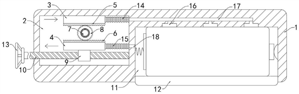
[0023] Such as figure 1 As shown, a power-saving lithium battery box that is easy to disassemble and assemble includes a box body 1. One end of the box body 1 is provided with an adjustment cavity 2, and the adjustment cavity 2 is slidably connected with an upper capacitor plate 3 and a lower capacitor plate 3 that are arranged horizontally. The capacitor plate 4, the upper capacitor plate 3 and the lower capacitor plate 4 constitute a capacitor. The upper and lower capacitor plates 3 and 4 are respectively fixedly connected to the upper rack 5 and the lower rack 6, and the upper rack 5 and The lower rack 6 is made of insulating material to prevent the upper capacitor plate 3 and the lower capacitor plate 4 from conducting.

[0024] The upper rack 5 and the lower rack 6 are provided with a rotating rod 7 which is rotatably connected with the adjusting cavity 2. The rotating rod 7 is rotatably connected with a gear 8 through a bearing. The rotating rod 7 and the gear 8 are also mad...

Embodiment 2

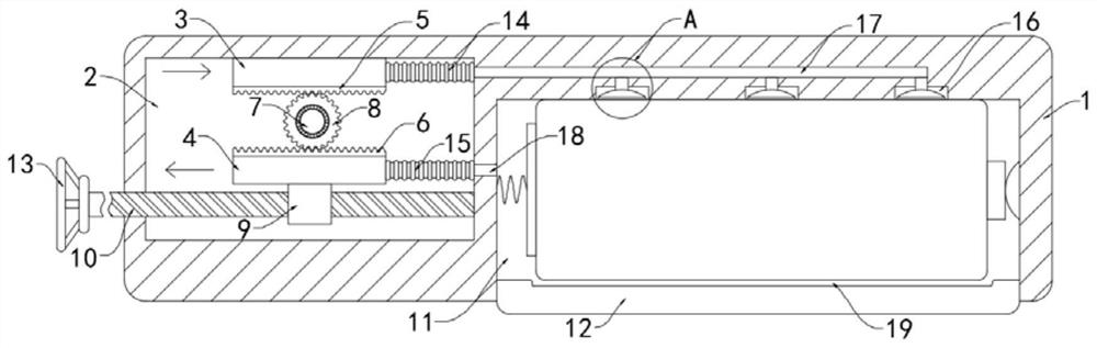
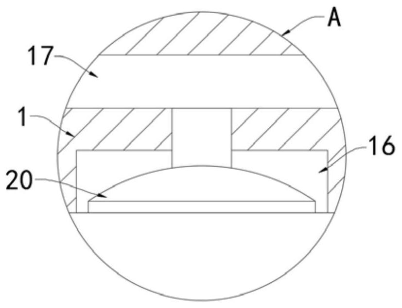
[0035] Such as Figure 2-3 As shown, the difference between this embodiment and the embodiment 1 is that the upper side wall of the protective cover 12 is recessed inward to form a fixing groove 19, and a suction cup 20 is fixedly installed in each placement groove 16, and each suction cup 20 is connected to The duct 17 communicates.

[0036] In this embodiment, the suction cup 20 can suck the battery when the air pressure in the placing groove 16 decreases, which further improves the fixing effect. When the battery receives a downward force, the battery will deviate from the horizontal force balance and move downward to be fixed. In the slot 19, when the protective cover 12 is opened, the battery will be squeezed out of the installation slot 11, making it easier to take out the battery.


PUM


Abstract

The invention belongs to the field of lithium battery boxes and in particular relates to a power-saving lithium battery box convenient to disassemble and assemble. The power-saving lithium battery boxcomprises a box body, and an adjusting cavity is formed in one end in the box body; an upper capacitor plate and a lower capacitor plate which are horizontally arranged are connected into the adjusting cavity in a sliding manner; opposite side walls of the upper capacitor plate and the lower capacitor plate are fixedly connected with an upper rack and a lower rack respectively; and a rotating rodrotationally connected with the adjusting cavity is arranged between the upper rack and the lower rack, a gear is rotationally connected to the rotating rod through a bearing, the upper end and the lower end of the gear are in engaged connection with the upper rack and the lower rack correspondingly, and a threaded sleeve is fixedly connected to the lower side wall of the lower capacitor plate. The upper capacitor plate and the lower capacitor plate are arranged and can be driven by the gear to move in two opposite directions, so that the vertical area between the two electrode plates is increased or decreased, the duration time of current in the whole circuit is controlled, corresponding adjustment can be performed according to different use conditions, waste of electric energy can be reduced, and the electric energy is greatly saved.

Description

Technical field [0001] The invention belongs to the field of lithium battery boxes, and particularly relates to a power-saving lithium battery box that is easy to disassemble and assemble. Background technique [0002] Lithium battery is one of many types of batteries, which can be divided into liquid lithium ion battery and polymer lithium ion battery. Since the 20th century, it has gradually been widely used in people's life and production. It has high energy storage, low weight, and service life. Changhe is green and environmentally friendly. [0003] Lithium batteries are usually installed in a matching lithium battery box. For some infrequently used electrical equipment such as remote controls, the lithium battery in the idle state in the battery box is easy to conduct air, and the phenomenon of power loss will occur, which will waste More power and reduced service life. In most traditional battery boxes, when installing the battery, the battery is simply fixed by the spring ...

Claims


Application Information

Patent Timeline
IPC IPC(8): H01M2/10
CPCY02E60/10
Inventor 田兴光
Owner 厦门派客新能源科技有限公司
Why Eureka
Try Eureka