
Cooling device

A cooling device and cooled technology, which is applied in the direction of cooling/ventilation device, electromechanical device, cooling/ventilation/heating transformation, etc., can solve the problems of increasing the size of the cooling device, disadvantages, etc.

Pending Publication Date: 2020-10-20
HUNAN LIANCHENG TRACK EQUIP CO LTD
View PDF0 Cites 0 Cited by
  • Summary
  • Abstract
  • Description
  • Claims
  • Application Information

AI Technical Summary

Problems solved by technology

Moreover, with the current trend of increasing speed and high efficiency, the specific structure that needs to be cooled will generate more heat, which in turn needs to further increase the volume of the cooling device
This is very unfavorable for use on diesel locomotives

Method used


Image

  • Cooling device
  • Cooling device
  • Cooling device

Examples


Embodiment Construction

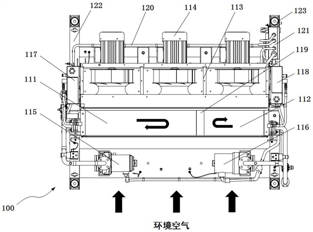
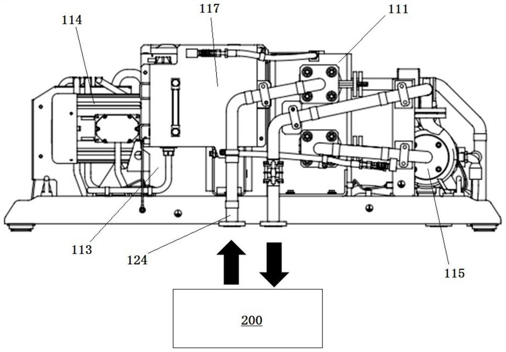
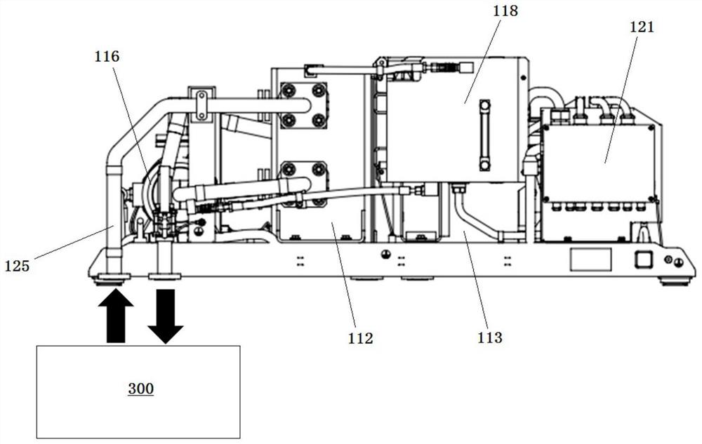
[0024] Figure 1 to Figure 3 An embodiment of a cooling device 100 according to the invention is shown schematically. The cooling device may adopt two cooling circuits to respectively cool the first cooled mechanism (eg, traction converter) 200 and the second cooled mechanism (eg, traction motor) 300 .

[0025] Such as figure 1 As shown, the cooling device 100 includes a radiator, and the radiator includes a first radiator 111 and a second radiator 112 arranged along the second horizontal direction. The cooling device 100 further includes a fan 113 arranged on one side of the radiator, that is, on one side of the first heat dissipation portion 111 and the second heat dissipation portion 112 along a first horizontal direction perpendicular to the second horizontal direction. The one fan 113 can be used to drive ambient air through the overlapping first heat dissipation portion 111 and the second heat dissipation portion 112 , thereby cooling the fluid in the first heat dissip...


PUM


Abstract

The invention relates to a cooling device which comprises a radiator, the radiator is connected with a cooled mechanism through a fluid pipeline; the fluid can flow between the cooled mechanism and the radiator through the fluid pipeline; and device also comprises a draught fan which is arranged on one side of the radiator in the first horizontal direction and connected with the radiator, and thedraught fan is constructed to drive air to flow to pass through the radiator so as to cool fluid in the radiator. The cooling device is beneficial to space utilization on an internal combustion locomotive.

Description

technical field [0001] The invention relates to the technical field of cooling of diesel locomotives, in particular to a cooling device. Background technique [0002] The cooling unit is a very important component on a diesel locomotive. Generally, a cooling device for independent cooling of a specific structure (for example, a traction converter, a traction motor, etc.) is provided on a diesel locomotive. This prevents these particular structures from failing due to overheating. [0003] At present, in order to achieve effective cooling, the volume of the cooling device is generally large, and the space occupied is correspondingly large. However, space on a diesel locomotive is limited. Moreover, with the current trend of increasing speed and high efficiency, the specific structure to be cooled will generate more heat, and further increase the volume of the cooling device. This is very unfavorable for use on diesel locomotives. [0004] Therefore, it is desirable to pr...

Claims


Application Information

Patent Timeline
Patent Type & Authority Applications(China)
IPC IPC(8): H02K9/04H02K9/19H05K7/20
CPCH02K9/04H02K9/19H05K7/20909H05K7/20927
Inventor 欧军晖胡金润吴凯王先海谭志雄李丹丹
Owner HUNAN LIANCHENG TRACK EQUIP CO LTD
Learn More