A constant power demagnetization device, method, storage medium and terminal equipment

A demagnetization device and constant power technology, which is applied in the control of generators, control systems, synchronous generators, etc., can solve the problems of low motor demagnetization speed and low safety

Active Publication Date: 2021-09-14
ELECTRIC POWER RES INST OF GUANGDONG POWER GRID
View PDF10 Cites 0 Cited by
  • Summary
  • Abstract
  • Description
  • Claims
  • Application Information

AI Technical Summary

Problems solved by technology

[0004] The embodiment of the present invention provides a constant power demagnetization device, method, storage medium and terminal equipment, which are used to solve the existing technical problems of low speed and low safety for motor demagnetization

Method used


Image

  • A constant power demagnetization device, method, storage medium and terminal equipment
  • A constant power demagnetization device, method, storage medium and terminal equipment

Examples


Embodiment 1

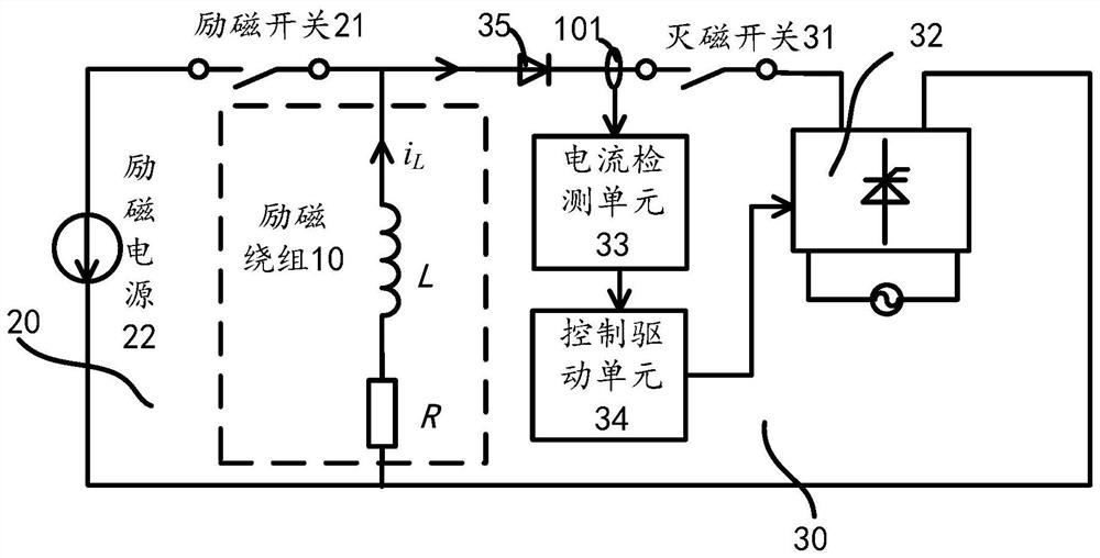
[0034] figure 1 It is a frame diagram of the constant power demagnetization device described in the embodiment of the present invention.

[0035] Such as figure 1As shown, the embodiment of the present invention provides a constant power de-excitation device, including an excitation winding 10, an excitation circuit 20 and a de-excitation circuit 30 connected in parallel with the excitation winding 10, and the de-excitation circuit 30 includes a de-excitation switch 31, a rectifier 32 , the current detection unit 33 and the control drive unit 34 connected with the current detection unit 33, the first end of the de-excitation switch 31 is connected with the first end of the current detection unit 33 and the excitation winding 10 respectively, the second end of the de-excitation switch 31 Connected to the rectifier 32, the control drive unit 34 is also connected to the rectifier 32, and the rectifier 32 is also connected to the second end of the field winding 10;

[0036] The ...

Embodiment 2

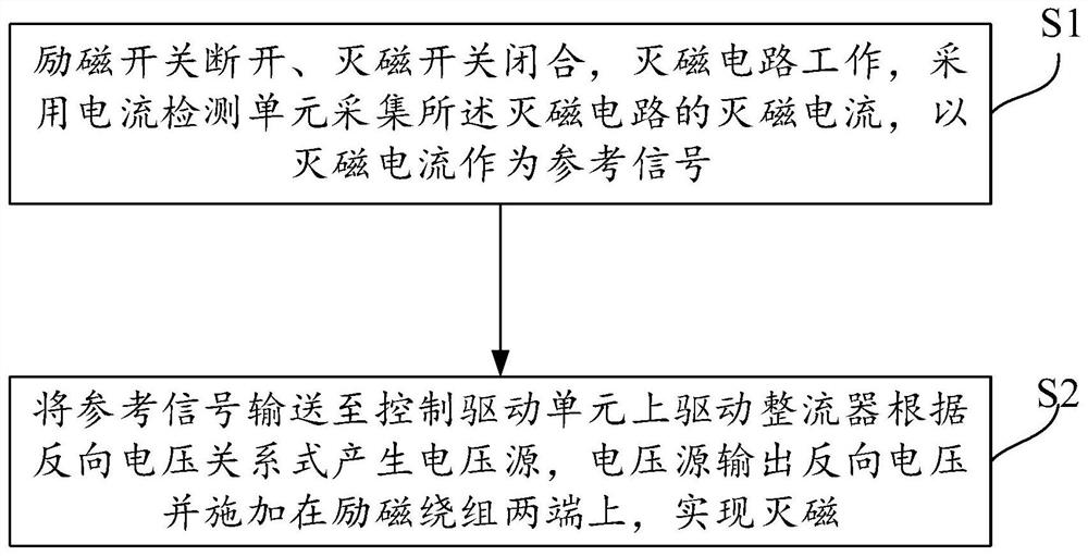
[0050] figure 2 It is a flow chart of the steps of the constant power demagnetization method described in the embodiment of the present invention.

[0051] Such as figure 2 As shown, the embodiment of the present invention also provides a constant power demagnetization method. The constant power demagnetization method based on the constant power demagnetization device of Embodiment 1 includes the following steps:

[0052] S1. The excitation switch is turned off, the de-excitation switch is closed, and the de-excitation circuit is working. The current detection unit is used to collect the de-excitation current of the de-excitation circuit, and the de-excitation current is used as a reference signal;

[0053] S2. Send the reference signal to the control drive unit to drive the rectifier to generate a voltage source according to the reverse voltage relational formula, and the voltage source outputs a reverse voltage and applies it to both ends of the excitation winding to real...

Embodiment 3

[0059] An embodiment of the present invention provides a computer-readable storage medium. The computer-readable storage medium is used to store computer instructions. When the computer-readable storage medium is run on a computer, it causes the computer to execute the above constant power demagnetization method.


PUM


Abstract

The embodiment of the present invention relates to a constant power de-excitation device, method, storage medium and terminal equipment, including an excitation winding, an excitation circuit and a de-excitation circuit. The de-excitation circuit includes a de-excitation switch, a rectifier, a current detection unit and a control drive unit. The first end of the de-excitation switch is respectively connected with the current detection unit and the first end of the excitation winding, the second end of the de-excitation switch is connected with the rectifier, the control drive unit is also connected with the rectifier, and the rectifier is also connected with the second end of the excitation winding The de-excitation current in the de-excitation circuit is obtained through the detection of the current detection unit, and the control drive unit controls the output reverse voltage of the voltage source generated by the rectifier according to the de-excitation current to apply to both ends of the excitation winding to ensure that the excitation winding is not in the process of de-excitation. The generation of overvoltage makes the constant power demagnetization device safe and reliable, and can realize rapid demagnetization, shorten the demagnetization time and improve the demagnetization efficiency; it solves the existing technology of low speed and low safety for motor demagnetization question.

Description

technical field [0001] The invention relates to the technical field of motor demagnetization, in particular to a constant power demagnetization device, method, storage medium and terminal equipment. Background technique [0002] De-excitation is one of the important functions of synchronous motor excitation system. When the motor is running normally, the rectifier of the excitation system supplies excitation current to the generator rotor through the de-excitation switch; when the motor stops normally or in an accident, the excitation power supply is cut off by the de-excitation switch, and at the same time the de-excitation switch is opened to access the de-excitation circuit, releasing the energy stored in the field winding. However, since the DC excitation winding of the motor usually has a large inductance characteristic, it is difficult to quickly transfer or eliminate the energy in it, and it is necessary to ensure that the voltage at both ends of the DC excitation wi...

Claims


Application Information

Patent Timeline
Patent Type & Authority Patents(China)
IPC IPC(8): H02P9/12H02P103/20
CPCH02P9/123H02P2103/20
Inventor 史正军梅桂华宋萌夏亚君李力梁飞苏伟钟国彬罗嘉程文锋赵兵蔡笋薛曼玉李达义
Owner ELECTRIC POWER RES INST OF GUANGDONG POWER GRID
Why Eureka
Try Eureka