Compressor torque compensation method and device

A torque compensation and compressor technology, which is applied in the control of electromechanical transmission, control of generators, motor control, etc., can solve problems such as uneven force

Active Publication Date: 2020-10-20
GREE ELECTRIC APPLIANCES INC
View PDF6 Cites 1 Cited by
  • Summary
  • Abstract
  • Description
  • Claims
  • Application Information

AI Technical Summary

Problems solved by technology

[0005] The embodiment of the present invention provides a compressor torque compensation method and device to solve the problem of uneven force when the compressor vibrates at low frequency

Method used


Image

  • Compressor torque compensation method and device
  • Compressor torque compensation method and device
  • Compressor torque compensation method and device

Examples


Embodiment Construction

[0058] In order to make the object, technical solution and advantages of the present invention clearer, the present invention will be described in further detail below in conjunction with the embodiments and accompanying drawings. Here, the exemplary embodiments and descriptions of the present invention are used to explain the present invention, but not to limit the present invention.

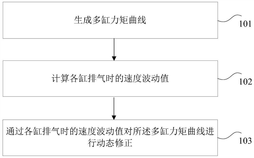
[0059] Considering that the torque in the mechanical cycle corresponding to each cylinder of the compressor is a single-cylinder torque curve, the final torque curve applied to the crankshaft is formed by superimposing the torque curves corresponding to each single cylinder. The suction and exhaust actions of the cylinders exist in the entire mechanical cycle of the compressor, and the suction and exhaust actions between the cylinders affect each other. Therefore, the compensation curve corresponding to each cylinder needs to change from time to time as the system load changes. , in order to ma...


PUM


Abstract

The invention provides a compressor torque compensation method and device, and the method comprises the steps: generating a multi-cylinder torque curve; calculating a speed fluctuation value when eachcylinder exhausts; and dynamically correcting the multi-cylinder torque curve according to the speed fluctuation value of each cylinder during exhaust. By means of the scheme, the problem that stressis uneven during low-frequency vibration of the compressor is solved, and the technical effect of guaranteeing the stable rotating speed of the compressor is achieved.

Description

technical field [0001] The invention relates to the technical field of equipment control, in particular to a compressor torque compensation method and device. Background technique [0002] In order to save more energy and improve the comfort of air conditioners, compressor frequency conversion drive control technology has been gradually used in air conditioners. With the improvement of compressor technology and the emergence of commercial multi-connected units, more and more commercial air conditioners can achieve more efficient and energy-saving goals. In order to make the compressor more energy-efficient, designs such as single-rotor compressors, double-rotor compressors, and three-rotor compressors have been designed. For example: dual-rotor compressors can also be divided into two-stage compressors and two-stage enthalpy-enhancing compressors, and can also be divided into equal-cylinder and unequal-cylinder compressors according to the cylinder structure. The cylinders...

Claims


Application Information

Patent Timeline
Patent Type & Authority Applications(China)
IPC IPC(8): H02P21/05H02P21/20H02P21/13H02P21/22H02P25/024H02P27/08F04C28/00
CPCH02P21/05H02P21/20H02P21/13H02P21/22H02P25/024H02P27/08F04C28/00H02P2207/05
Inventor 宋现义李洋方小斌刘文斌杨帆刘顺
Owner GREE ELECTRIC APPLIANCES INC
Why Eureka
Try Eureka