Walking stick capable of performing airflow type heat dissipation on palm center

An air flow, crutch technology, applied in the field of crutches, can solve problems such as the effect of affecting the heat dissipation of crutches

Inactive Publication Date: 2020-10-23
计彩华
View PDF7 Cites 1 Cited by
  • Summary
  • Abstract
  • Description
  • Claims
  • Application Information

AI Technical Summary

Problems solved by technology

[0006] 1. Since multiple electrical components are involved, the work of the electrical components will generate heat, which will affect the heat dissipation effe

Method used


Image

  • Walking stick capable of performing airflow type heat dissipation on palm center
  • Walking stick capable of performing airflow type heat dissipation on palm center
  • Walking stick capable of performing airflow type heat dissipation on palm center

Examples


Embodiment 1

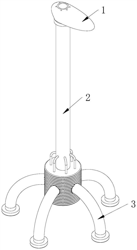
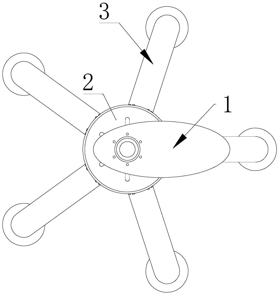
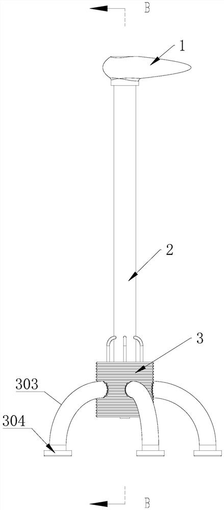
[0038] A crutch capable of dissipating heat from the center of the palm by airflow, comprising a crutch handle 1, a crutch shaft 2, a crutch base 3, the crutch base 3, the crutch shaft 2 and the crutch handle 1 are connected in sequence, and the crutch shaft 2 is located below the outer surface A plurality of through holes 4 are provided;

[0039]The crutch base 3 includes a corrugated cylinder 301, and the center of the bottom of the corrugated cylinder 301 is provided with a valve 302, which can collect sweat or infiltrated rainwater and open the valve 302 for discharge, which will not cause future use problems. The outer surface of the corrugated cylinder 301 There are a plurality of curved support legs 303 equidistantly arranged. The middle of the curved support legs 303 is hollow and communicated with the bellows 301. The connected curved support legs 303 can be used when the user is walking Any curved support leg 303 supporting the ground will squeeze the corrugated tube...

Embodiment 2

[0043] On the basis of Embodiment 1, the surface of the inner wall of the crutch shaft 2 is fixedly connected with the limit ring 5 located on the outside of the air flow hose 307, and the inside of the limit ring 5 is set in a spiral state, and the limit ring 5 set in the spiral state The ring 5 better protects the airflow hose 307, and it will not be easily dropped and affect the use.

Embodiment 3

[0045] On the basis of Embodiment 1 and Embodiment 2, the crutch handle 1 includes a rubber handle 101, the upper surface of the rubber handle 101 is provided with a plurality of air holes 102, the bottom of the rubber handle 101 is provided with a round hole 103, and the air flow hose The top of 307 communicates with the bottom of the rubber handle 101. By setting the airflow hole 102, the rubber handle 101, the airflow hose 307 and the round hole 103, a part of the airflow flows from the airflow hose 307 and finally reaches the rubber handle 101. Inside, it flows out from the airflow hole 102 to dissipate heat from the palm of the hand and the outside of the palm of the hand, and the other part of the airflow is directly squeezed through the corrugated tube 301 and flows to the round hole 103, and performs centralized heat dissipation on the palm , the effect is faster, and does not involve electrical components, and will not affect the heat dissipation of the crutch.

[004...


PUM


Abstract

The invention belongs to the technical field of walking sticks, and particularly relates to a walking stick capable of performing airflow type heat dissipation on the palm center. A walking stick capable of conducting airflow type heat dissipation on the palm center comprises a walking stick handle, a walking stick rod barrel and a walking stick base, wherein the walking stick base, the walking stick rod barrel and the walking stick handle are sequentially connected, a plurality of through holes are formed in the lower portion of the outer surface of the walking stick rod barrel, the walking stick base comprises a corrugated barrel, and a valve is arranged in the center of the bottom of the corrugated barrel. The walking stick base, the walking stick rod barrel and the walking stick handleare arranged; when a user walks, after contact with the ground, the corrugated barrel is extruded to form airflow flowing, one part of the airflow flows into the walking stick handle through the airflow type hose to cool the palm of a user, the other part of the airflow directly flows into the walking stick handle from the walking stick rod barrel to cool the palm center of the user, the effect is faster, no electric appliance element is involved, and heat dissipation of the walking stick cannot be affected.

Description

technical field [0001] The invention belongs to the technical field of crutches, and in particular relates to a crutch capable of dissipating heat from the center of the palm by air flow. Background technique [0002] Crutches are an important aid in medical rehabilitation, such as split sticks, elbow sticks, and axillary sticks. Among them, the cane is mainly used for mild needs, such as the elderly or climbers. However, due to the single function of the traditional crutches, the palms of the crutches tend to sweat when held for a long time, which is not only very uncomfortable, but also prone to slipping and inconvenient to use. [0003] As disclosed in CN210205295U, a splicing crutch that is easy to fold and store includes a first stick body and a sleeve. The bottom end of the first stick body is connected with a stainless steel hinge through a bolt. The heat dissipation through holes come out, so that the porous handle has a good heat dissipation and ventilation effect,...

Claims


Application Information

Patent Timeline
IPC IPC(8): A45B3/00A45B9/00A45B9/02
CPCA45B3/00A45B9/00A45B9/02A45B2009/002
Inventor 计彩华
Owner 计彩华
Why Eureka
Try Eureka