Storage rack for selling electronic products

A technology for electronic products and storage racks, applied in applications, display hangers, display shelves, etc., can solve the problems of electronic product sales impact, dust adhesion, etc.

Inactive Publication Date: 2020-10-23
SUZHOU QIMAO INFORMATION TECH CO LTD
View PDF1 Cites 0 Cited by
  • Summary
  • Abstract
  • Description
  • Claims
  • Application Information

AI Technical Summary

Problems solved by technology

An electronic product sorting rack for electronic product sales in the above-mentioned patent has the following disadvantages: when the existing storage rack sto

Method used


Image

  • Storage rack for selling electronic products
  • Storage rack for selling electronic products
  • Storage rack for selling electronic products

Examples


Embodiment 1

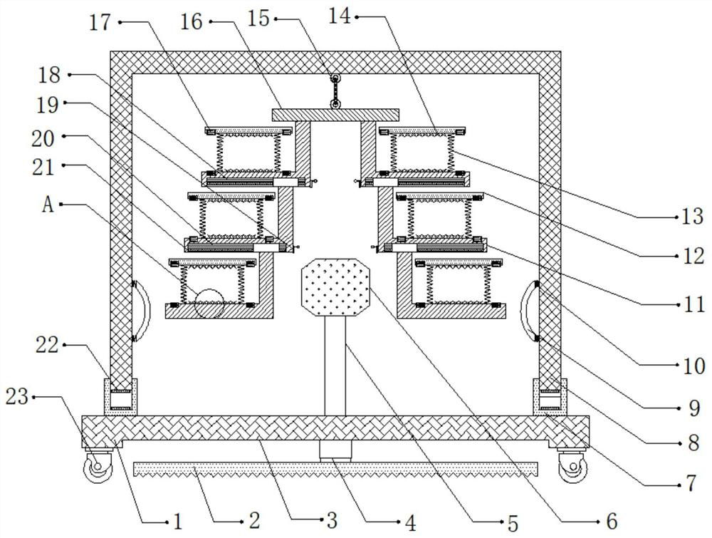
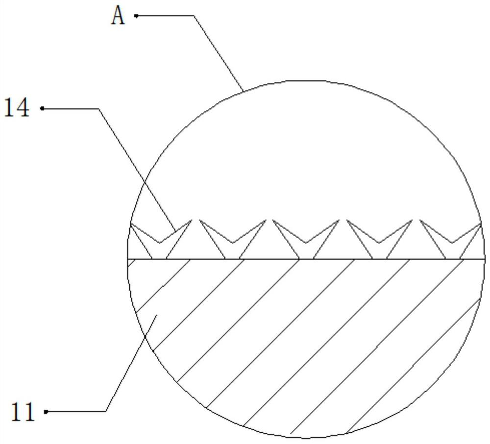
[0029] refer to Figure 1-3 , a storage rack for selling electronic products, comprising a fixed seat 1, the two sides of the outer wall of the top of the fixed seat 1 are connected with a sleeve 7 by bolts, and the inner wall of the sleeve 7 is slidably connected with a fixed frame 8, and the top of the fixed frame 8 The inner wall is bolted with a rope 15, and the bottom outer wall of the rope 15 is bolted with a fixed plate 16, and both sides of the outer wall at the bottom of the fixed plate 16 are connected with a storage plate 11 by bolts, and the bottom outer wall of the storage plate 11 is provided with a fixed groove 18, The inner walls of both sides of the fixed groove 18 are connected with threaded rods 21 through bearings, and the outer walls of the threaded rods 21 are threaded with threaded blocks. The threaded blocks and the storage plate 11 are connected by bolts. A fixed rod 5 is connected with a bolt, and the top outer wall of the fixed rod 5 is connected wit...

Embodiment 2

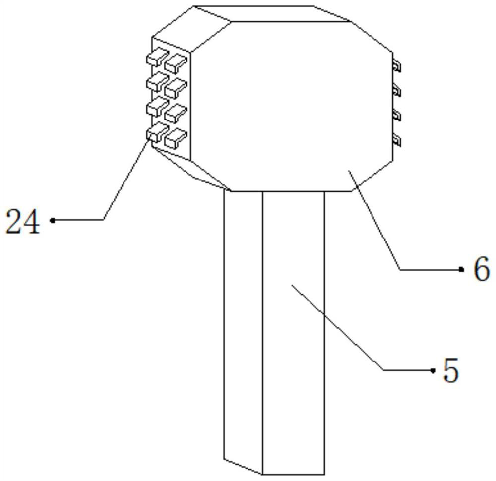
[0040] refer to Figure 4 , a storage rack for sales of electronic products. Compared with Embodiment 1, the top outer wall of the fixing seat 1 and the impact hammer 6 are connected by a hinge, and the outer walls on both sides of the impact hammer 6 and the fixing seat 1 A third spring 25 is connected by bolts. When a collision occurs between the storage plate 11 and the impact hammer 6, the elastic properties of the third spring 25 make the impact hammer 6 swing back and forth, thereby improving the contact between the storage plate 11 and the impact hammer 6. Impact frequency, so that electronic products can be effectively dedusted.

[0041] Working principle: When in use, the storage rack is moved to a suitable position through the roller 23. After the movement is completed, the hydraulic rod 4 is activated, and the hydraulic rod 4 will drive the rack 2 to move down, thereby fixing the storage rack. After the fixing is completed, The electronic products that need to be s...


PUM


Abstract

The invention discloses a storage rack for selling electronic products, which comprises a fixingseat.Sleeves are fixedly connected to the two sides of the outer wall of the top of the fixing seat. Theinner wall of the sleeve is slidably connected with a fixing frame. A rope is bolted to the inner wall of the top of the fixing frame. A fixing plate is bolted to the outer wall of the bottom of therope; storage plates are fixedly connected to the two sides of the outer wall of the bottom of the fixing plate, fixing grooves are formed in the outer walls of the bottoms of the storage plates, threaded rods are rotatably connected between the inner walls of the two opposite sides of the fixing grooves through bearings, threaded blocks are in threaded connection with the outer walls of the threaded rods, and the threaded blocks are connected with the storage plates through bolts. The dust removal efficiency of electronic products can be improved, dust adhering to the electronic products canbe removed, the situation that the surface of the electronic products is polluted due to the fact that the dust is accumulated on the storage plate can be prevented, the impact frequency of the storage plate and the impact hammer can be improved, and the electronic products can be conveniently subjected to dust removal treatment.

Description

technical field [0001] The invention relates to the technical field of electronic products, in particular to a storage rack for selling electronic products. Background technique [0002] Electronic products are related products based on electric energy. In the process of selling electronic products, racks are needed to classify and display them, so as to facilitate the sale of electronic products. [0003] After retrieval, the Chinese patent authorization number is CN110973919A, which discloses an electronic product classification rack for electronic product sales, including a bottom plate, and movable wheels are fixedly installed on the left and right sides of the bottom of the bottom plate. The electronic product classification rack for electronic product sales, the fastening block is stored in the installation cavity and separated from the fixing groove, the fixing of the horizontal plate and the support stand can be released, and the installation cap is unscrewed to make...

Claims


Application Information

Patent Timeline
IPC IPC(8): A47F5/10A47F5/00B08B5/02B08B7/02
CPCA47F5/0025A47F5/0093A47F5/10B08B5/02B08B7/02
Inventor 周俊明
Owner SUZHOU QIMAO INFORMATION TECH CO LTD
Why Eureka
Try Eureka