Screening and output integrated particle screening system

A particle screening technology, applied in solid separation, filtration, transportation and packaging, etc., to achieve fast and efficient screening, speed up screening efficiency, and prevent the accumulation of small particles

Active Publication Date: 2022-02-08
安徽多广新材料科技有限公司
View PDF7 Cites 0 Cited by
  • Summary
  • Abstract
  • Description
  • Claims
  • Application Information

AI Technical Summary

Problems solved by technology

The disadvantage of this invention is that it cannot carry out efficient screening of large and small particles

Method used


Image

  • Screening and output integrated particle screening system
  • Screening and output integrated particle screening system
  • Screening and output integrated particle screening system

Examples


specific Embodiment approach 1

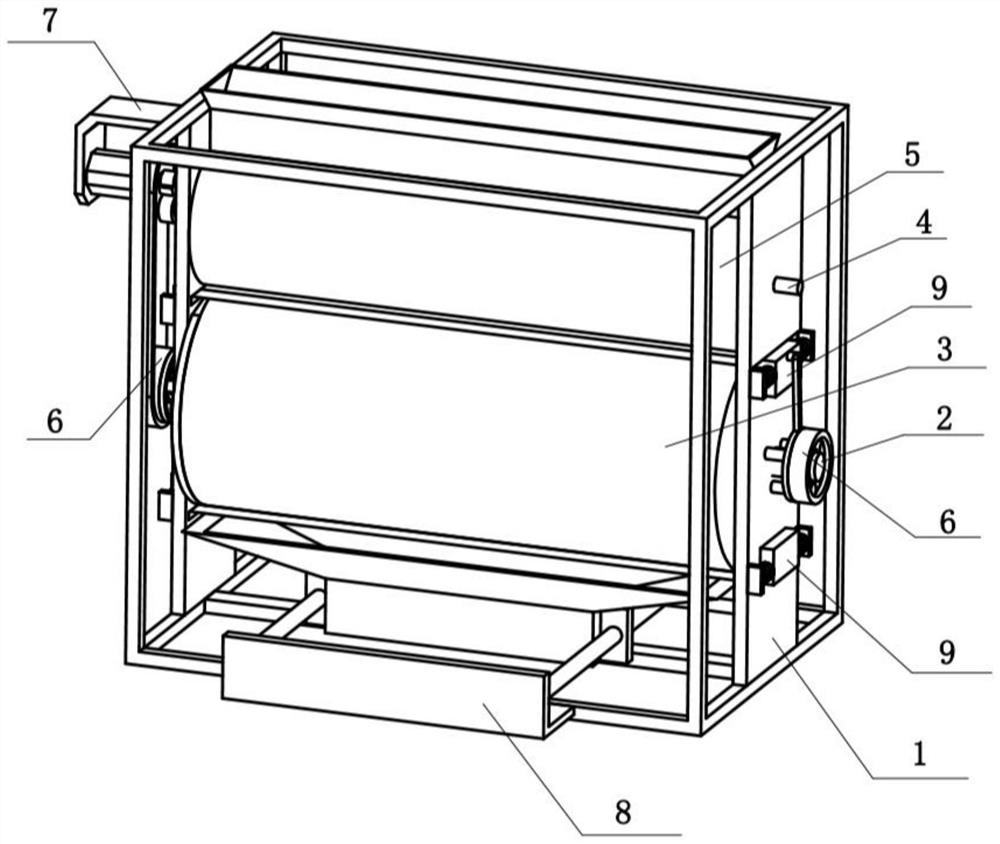
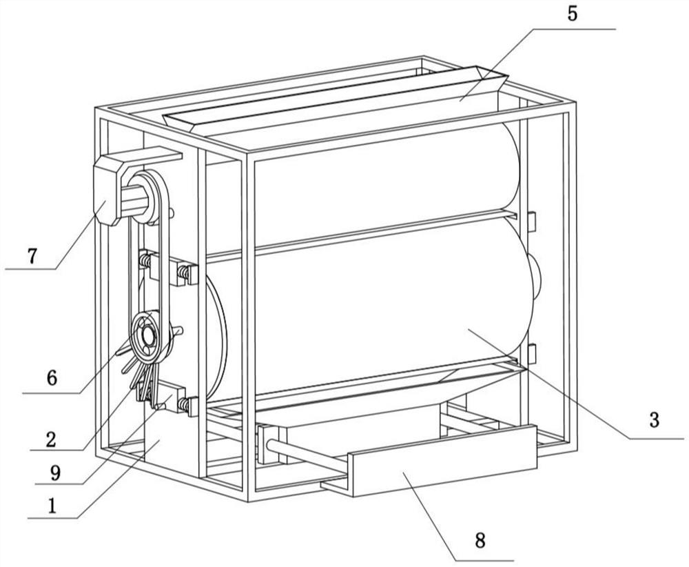
[0034] Combine below Figure 1-11 Describe this embodiment, the particle screening system with integrated screening and output includes a support assembly 1, a drive assembly 7 and an output assembly 8, the drive assembly 7 is fixedly connected to the upper part of the left side of the support assembly 1, and the output assembly 8 is fixedly connected to the support assembly 1 At the lower end of the screen, the particle screening system with integrated screening and output also includes a screening assembly 2, a screening bucket 3, a feeding assembly 4, a storage assembly 5, a differential assembly 6 and an opening and closing assembly 9. The screening assembly 2 is rotatably connected to the support The lower part of the assembly 1, the screening bucket 3 is fixedly connected to the lower part of the support assembly 1, the feeding assembly 4 is rotatably connected to the upper part of the support assembly 1, the storage assembly 5 is fixedly connected to the upper part of th...

specific Embodiment approach 2

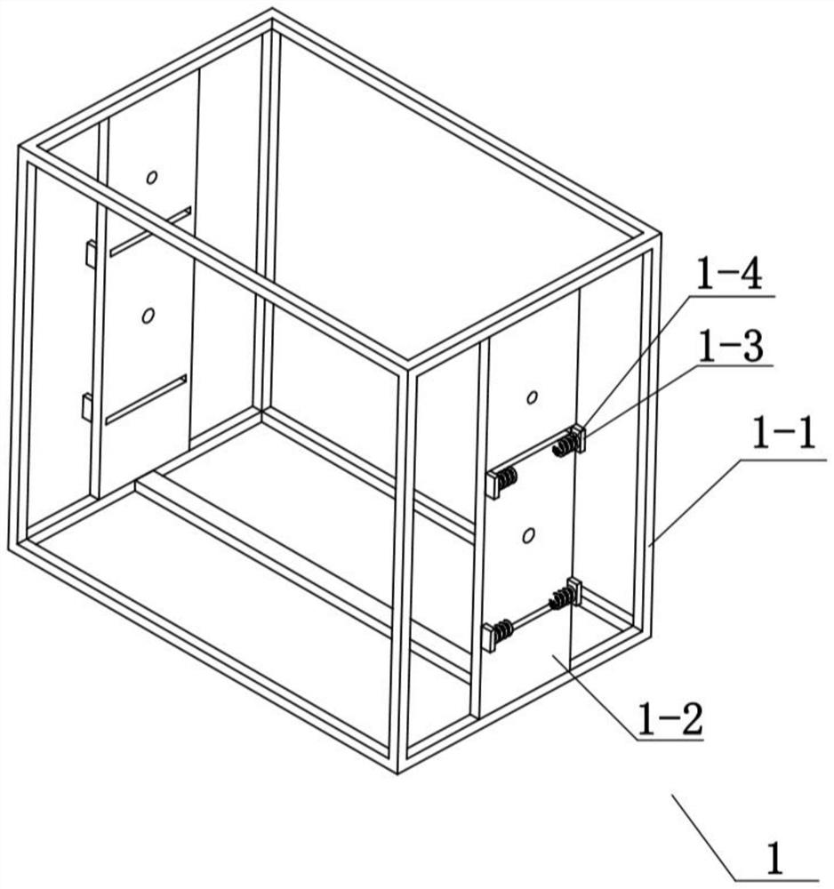
[0036] Combine below Figure 1-11 To illustrate this embodiment, the support assembly 1 includes a support frame 1-1, a side support plate 1-2, a spring plate 1-3 and a return spring 1-4, and the two side support plates 1-2 are respectively fixedly connected to the support frame On the left and right sides of 1-1, two spring plates 1-3 are arranged on the front and rear sides of the two side support plates 1-2, and a plurality of spring plates 1-3 are fixedly connected with reset springs 1-4; A side support plate 1-2 plays a role in supporting and installing the remaining components. After being compressed and stretched by the two opening and closing components 9, when the applied external force disappears, the plurality of return springs will 1-4 play a role in resetting the two opening and closing components 9 .

specific Embodiment approach 3

[0037] Combine below Figure 1-11 To illustrate this embodiment, the screening assembly 2 includes a screening plate 2-1, a screening hole 2-2, a screening shaft 2-3 and a cover 2-4, and the screening plate 2-1 is provided with a plurality of The screening hole 2-2, the left and right sides of the screening plate 2-1 are fixedly connected to the screening shaft 2-3, the cover 2-4 is fixedly connected to the left side support plate 1-2, and the two screens The sub-shafts 2-3 are respectively rotatably connected to the two side support plates 1-2, and the sieving shaft 2-3 on the left side is rotatably connected to the cover 2-4.

[0038] When the sieving plate 2-1 rotates, small particles will pass through multiple sieving holes 2-2 from one side of the sieving plate 2-1 and fall to the other side. The rotation of the sieving plate 2-1 prevents particles Accumulation, resulting in low screening efficiency, this form of rotation will allow small particles to be better separated...


PUM


Abstract

The present invention relates to the technical field of screening, more specifically, a particle screening system with integrated screening and output, including a support assembly, a screening assembly, a screening bucket, a feeding assembly, a storage assembly, a differential assembly, a driving assembly, and an output assembly And the opening and closing assembly, the driving assembly can drive the left differential assembly to rotate, the left differential assembly drives the screening assembly to rotate multiple times, separates particles of different sizes, and the screening assembly drives the right differential assembly to rotate. The speed assembly rotates, and when the differential assembly on the left drives the opening and closing assembly at the lower end to slide, a discharge of small particles is carried out. Fast and efficient screening.

Description

technical field [0001] The invention relates to the technical field of screening, in particular to a particle screening system with integrated screening and output. Background technique [0002] The CN109941756A invention with the publication number of discloses a particle screening method and a powder fluidization device. The particle screening method includes: using the powder receiving mode, the powder fluidization mode, and the powder output mode of the powder fluidization device; Before the powder fluidization mode or in the powder fluidization mode, set the specified air pressure value or pressure value range in the cavity where the gas-solid two-phase flow is mixed, and keep the air pressure stable at the specified air pressure in the powder fluidization mode In the powder output mode, keep the air pressure within the specified air pressure value or air pressure value interval and extract the corresponding gas-solid two-phase flow under the specified air pressure valu...

Claims


Application Information

Patent Timeline
Patent Type & Authority Patents(China)
IPC IPC(8): B07B1/28B07B1/42B07B1/46B65G65/48
CPCB07B1/288B07B1/42B07B1/46B65G65/4881
Inventor 章庆聪
Owner 安徽多广新材料科技有限公司
Why Eureka
Try Eureka