
T-shaped vacuum induction smelting and casting furnace

A vacuum induction smelting and vacuum smelting technology, which is applied in ingot workshops, casting workshops, casting equipment, etc., can solve problems such as low casting efficiency, broken holes in the furnace, and products that do not meet the requirements

Inactive Publication Date: 2020-10-23
SUZHOU ZHENHU ELECTRIC FURNACE +1
View PDF7 Cites 3 Cited by
  • Summary
  • Abstract
  • Description
  • Claims
  • Application Information

AI Technical Summary

Problems solved by technology

[0002] Vacuum induction melting is a method of smelting by using electromagnetic induction to generate eddy current in the metal conductor to heat the furnace material under vacuum conditions. The metal is melted and then used for casting; while the existing vacuum induction melting casting furnace generally has one-way ingot ingot. , that is, the ingot enters the vacuum chamber to evacuate and then enters the melting and casting furnace, then pours molten steel into the ingot, and then sends the ingot out through the original outlet, so that there will be many uncontrollable factors in the middle that lead to The casted products do not meet the requirements, and the casting efficiency is still low
[0003] The one-way entry and exit of the ingot into and out of the vacuum melting casting furnace may cause the furnace to break through, breaking the vacuum environment in the vacuum melting casting furnace. The change of the vacuum environment will affect the quality of the molten steel in the furnace, thereby affecting the casting quality of the ingot. For this reason, we On the basis of the original vacuum induction furnace, according to the characteristics of high-end products in the foundry industry, a new generation of T-shaped casting system vacuum induction furnace was innovatively developed to meet the requirements of the high-end foundry industry. Product requirements for speed temperature and different cooling states

Method used


Image

  • T-shaped vacuum induction smelting and casting furnace
  • T-shaped vacuum induction smelting and casting furnace
  • T-shaped vacuum induction smelting and casting furnace

Examples


Embodiment Construction

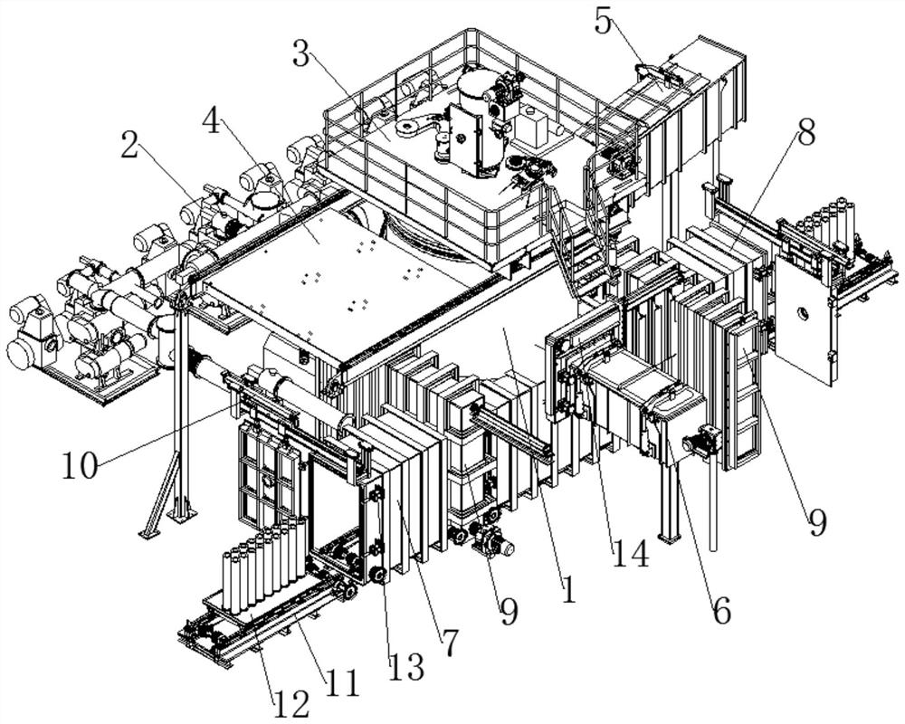
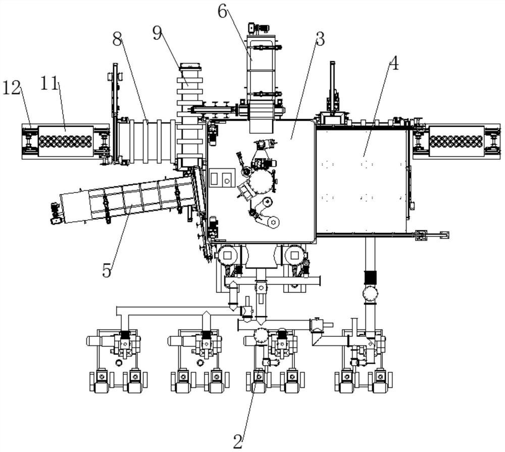
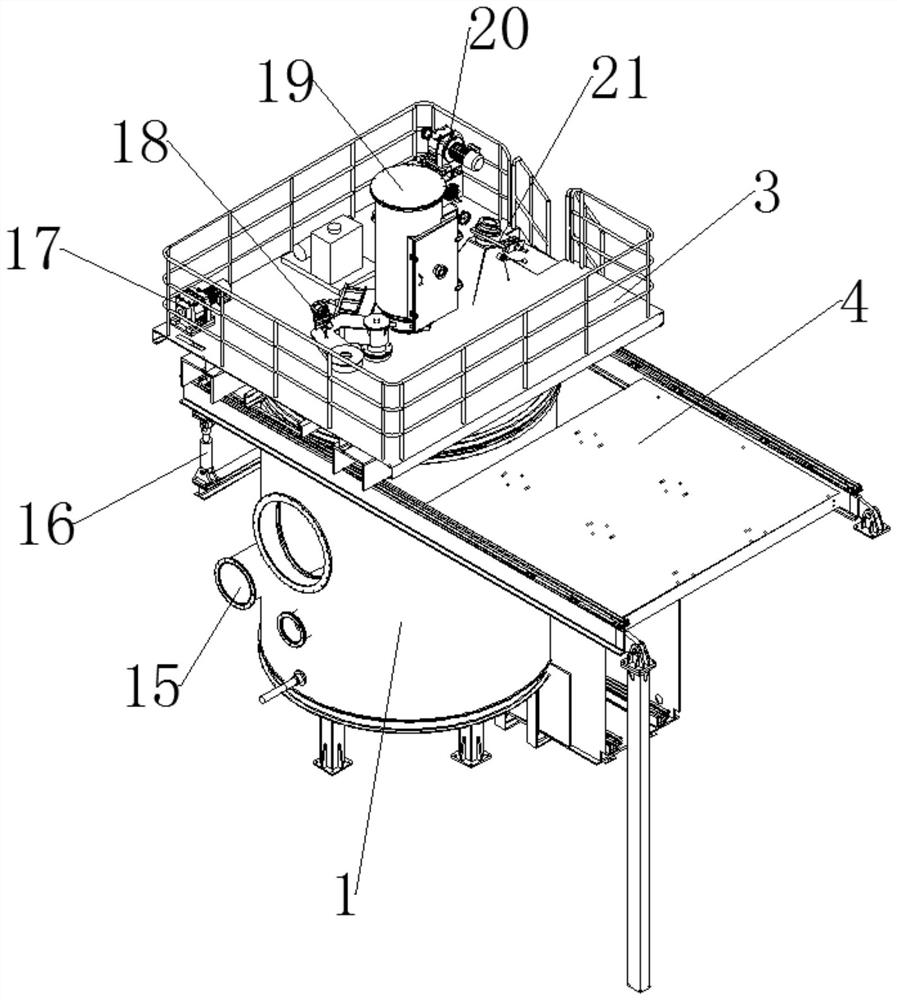
[0027] The present invention is specifically described below in conjunction with accompanying drawing, as Figure 1-6 As shown, the T-type vacuum induction melting casting furnace mainly includes the following structures: a vacuum melting chamber 1, in which metal melting and casting are carried out; a melting furnace 23, installed in the vacuum melting chamber 1 for melting metal; There are four vacuum valves 2, which are respectively arranged outside the vacuum smelting chamber 1, connected to the vacuum smelting chamber 1 through pipes, and different vacuum levels can be achieved by switching the inside of the vacuum smelting chamber 1 in different forms; moving the furnace cover 3 , installed on the top of the vacuum melting chamber 1, the inside of the vacuum melting furnace 23 can be overhauled and parts replaced by opening the movable furnace cover 3; side, which plays the role of buffering; the transmission device 11 runs through the entire vacuum melting chamber 1, th...


PUM


Abstract

The invention discloses a T-shaped vacuum induction smelting and casting furnace. The furnace comprises a vacuum smelting chamber, a smelting furnace arranged inside the vacuum smelting chamber and vacuum valves connected with the vacuum smelting chamber through pipelines, wherein the top of the vacuum smelting chamber is provided with a movable furnace cover, the vacuum smelting chamber is provided with two outlets, and the two outlets are respectively provided with a mold inlet chamber and a mold outlet chamber. The T-shaped vacuum induction smelting and casting furnace further comprises a flow groove chamber and a side feeding chamber, wherein the flow groove chamber is arranged outside the vacuum smelting chamber and communicates with the vacuum smelting chamber for guiding molten steel in the smelting furnace into an ingot mold; and the side feeding chamber is arranged outside the vacuum smelting furnace and communicates with the vacuum smelting chamber for feeding the smelting furnace. By arranging the mold inlet chamber and the mold outlet chamber, the time influence of casting circulation and frequent switching of the vacuum degree are greatly reduced, a large amount of energy consumption is saved, streamlined casting production can be realized, and the casting efficiency of castings is improved.

Description

technical field [0001] The invention relates to the technical field of metal vacuum melting and casting, in particular to a T-shaped vacuum induction melting and casting furnace. Background technique [0002] Vacuum induction melting is a method of smelting by using electromagnetic induction to generate eddy current in the metal conductor to heat the furnace material under vacuum conditions. The metal is melted and then used for casting; while the existing vacuum induction melting casting furnace generally has one-way ingot ingot. , that is, the ingot enters the vacuum chamber to evacuate and then enters the melting and casting furnace, then pours molten steel into the ingot, and then sends the ingot out through the original outlet, so that there will be many uncontrollable factors in the middle that lead to The casted products do not meet the requirements, and the casting efficiency is still low. [0003] The one-way entry and exit of the ingot into and out of the vacuum m...

Claims


Application Information

Patent Timeline
IPC IPC(8): B22D9/00B22D7/12
CPCB22D7/12B22D9/00B22D27/15
Inventor 朱兴发周慧俊陈睿朱敏陈紫瑶
Owner SUZHOU ZHENHU ELECTRIC FURNACE
Learn More