Loading suction cup assembly device

An assembly device and suction cup technology, applied in the direction of transportation and packaging, conveyor objects, etc., can solve the problems of reduced production efficiency, inconvenient use, and long time consumption

Inactive Publication Date: 2020-10-23
南通金泰科技有限公司
View PDF10 Cites 1 Cited by
  • Summary
  • Abstract
  • Description
  • Claims
  • Application Information

AI Technical Summary

Problems solved by technology

However, before and after lifting, the lifting equipment either uses a hook to directly hook the workpiece to transfer, or uses a rope to bind the workpiece and then transfers. The former method will cause damage to t

Method used


Image

  • Loading suction cup assembly device
  • Loading suction cup assembly device
  • Loading suction cup assembly device

Examples


Embodiment Construction

[0024] The following will clearly and completely describe the technical solutions in the embodiments of the present invention with reference to the accompanying drawings in the embodiments of the present invention. Obviously, the described embodiments are only some, not all, embodiments of the present invention. Based on the embodiments of the present invention, all other embodiments obtained by persons of ordinary skill in the art without making creative efforts belong to the protection scope of the present invention.

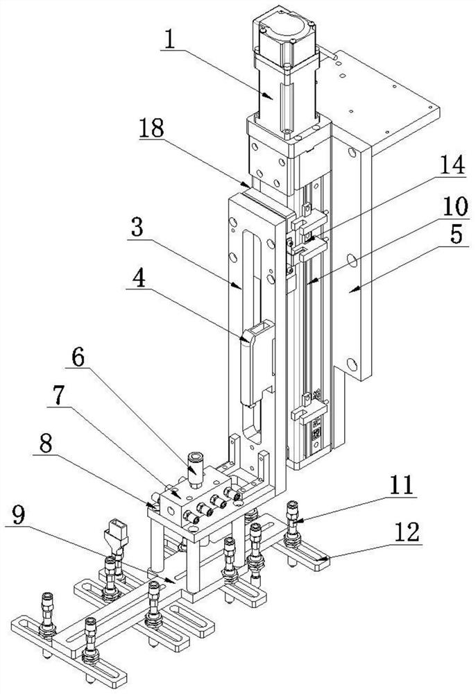
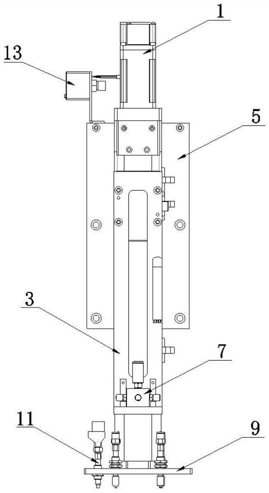
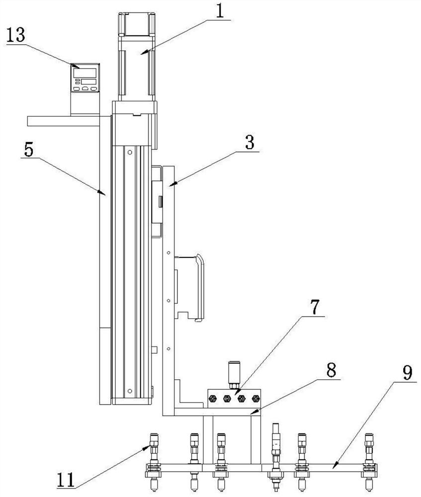
[0025] see Figure 1-4 , the present invention provides a technical solution: a feeding suction cup assembly device, including a feeding suction cup assembly device 18, a Z-axis electric cylinder fixing plate 5 is arranged on the feeding suction cup assembly device 18, and a Z-axis electric cylinder fixing plate 5 A support column 10 is provided in the center of the front side, a Z-axis electric cylinder 1 is provided on the top of the support column 10 , and ...


PUM


Abstract

The invention discloses a loading suction cup assembly device. The device comprises the loading suction cup assembly device which is provided with a Z-axis motor fixing plate, wherein the center of the front side of the Z-axis motor fixing plate is provided with a support column, the top of the support column is equipped with a Z-axis electric cylinder, the outer side of the support column is equipped with a suction cup support column mounting plate, a substrate loading suction arm drag chain rack is provided between the suction cup support column mounting plate and the support column, one side of the substrate loading suction arm drag chain rack is fixedly connected to the side of the suction cup support column mounting plate, the clip on the substrate loading suction arm drag chain rackis set in a chute on the side of the support column, the front side of the bottom end of the suction cup support column mounting plate is provided with a suction cup bracket mounting plate, and suction cups are arranged on the suction cup brackets on both sides of the suction cup bracket mounting plate. The loading suction cup assembly device has a reasonable design and can realize efficient and stable picking and placing of the suction cups.

Description

technical field [0001] The invention relates to the technical field of chip loading suction cup assembly, in particular to a feeding suction cup assembly device. Background technique [0002] During the processing and production of large workpieces, they often need to be transferred from one station to another, or from one production line to another, which requires the use of lifting equipment to lift and carry them. However, before and after lifting, the lifting equipment either uses a hook to directly hook the workpiece to transfer, or uses a rope to bind the workpiece and then transfers. The former method will cause damage to the surface of the workpiece, which is not conducive to the processing of the workpiece. The latter method is tied And the loosening operation is complicated, inconvenient to use, time-consuming, and will reduce production efficiency. Contents of the invention [0003] The purpose of the present invention is to provide a loading sucker assembly de...

Claims


Application Information

Patent Timeline
IPC IPC(8): B65G47/91
CPCB65G47/912B65G47/918
Inventor 刘建峰姚海峰黄小星葛军
Owner 南通金泰科技有限公司
Why Eureka
Try Eureka