
A kind of encapsulation machine and encapsulation method

A glue wrapping machine and glue wrapping technology, which is applied in the field of glue wrapping machines, can solve the problems that the heat sink cannot be clamped, the heat sink is easy to loosen, and the glue wrap is not in place.

Active Publication Date: 2022-07-29
群光电能科技(重庆)有限公司
View PDF0 Cites 0 Cited by
  • Summary
  • Abstract
  • Description
  • Claims
  • Application Information

AI Technical Summary

Problems solved by technology

[0003] The invention provides an encapsulation machine and an encapsulation method, which solves the technical problem that the existing biaxial encapsulation machine cannot clamp the heat sink during the encapsulation process, resulting in the heat sink being prone to loosening during the encapsulation process. Lagging is not in place

Method used


Image

  • A kind of encapsulation machine and encapsulation method
  • A kind of encapsulation machine and encapsulation method
  • A kind of encapsulation machine and encapsulation method

Examples


Embodiment Construction

[0065] The following is a further detailed description through specific embodiments:

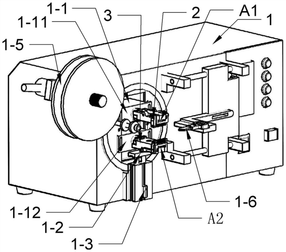
[0066] In order to realize the clamping of the encapsulated parts by the double-shaft encapsulation machine, take the encapsulated part as an example with a heat sink with a metal body on the surface, such as Figure 1-5 As shown, the present embodiment provides an encapsulation machine, including:

[0067] The main body 1 of the laminating machine, and the first clamp 2 and the second clamp 3 fixedly installed on the main body 1 of the laminating machine. The first clamp 2 clamps the first heat sink A1, and the second clamp 3 clamps the first heat sink Two heat sink A2.

[0068] (1) The first jig 2 and the second jig 3

[0069] In this embodiment, the structures of the first clamp 2 and the second clamp 3 are the same, and the specific structure of each clamp will be described below by taking the first clamp 2 as a representative.

[0070] The first fixture 2 includes:

[0071] 1) the l...


PUM


Abstract

The invention relates to the field of rubber encapsulation machines, and specifically discloses a rubber encapsulation machine and a rubber encapsulation method. The rubber encapsulation machine includes two clamps; side; the upper clamp block, which is covered on the lower clamp block, has the opposite third short side and fourth short side, respectively corresponding to the first short side and the second short side; the clamp lower block and the clamp upper A space for installing the rubber-coated parts is formed between the blocks; the rubber-coated parts are inserted into the installation space of the rubber-coated parts from the opening between the second short side and the fourth short side, leaving the rubber-coated position outside; the spring assembly , is provided with a spring; one end of the spring is fixed on one side of the second short side, and the other end is rotatably fixed on one side of the fourth short side, and one side of the fourth short side is opposite to one side of the second short side. The lower part of the jig, the upper part of the jig, and the spring components are designed to cooperate with each other to ensure the stability of the encapsulated parts during encapsulation, to avoid their loosening, and to ensure the quality of the encapsulation.

Description

technical field [0001] The invention relates to the field of encapsulation machines, in particular to an encapsulation machine and an encapsulation method. Background technique [0002] The commonly used crystal heat sinks on the PCB need to be insulated to avoid interference with the electronic components on the PCB. At present, the commonly used method of insulation treatment is to wrap insulating tape. Because there are many irregular grooves and other parts and screws on the heat sink, it is difficult to design the rubber-coated jig. Generally, the insulation tape is manually wrapped, and the efficiency is low. For example, if 10,000 pieces are produced per day, it takes 5-6 people to complete. . In order to increase the lagging efficiency, a biaxial tape machine has appeared at present, but the biaxial tape machine cannot clamp the heat sink during the lagging process, which causes the heat sink to loosen during the lagging process, and the lagging does not work. in ...

Claims


Application Information

Patent Timeline
Patent Type & Authority Patents(China)
IPC IPC(8): B65H35/07B65H35/00B23Q3/06H05K3/00
CPCB65H35/06B65H35/0073B23Q3/06H05K3/00
Inventor 林哲仕张伟欣胥勋举
Owner 群光电能科技(重庆)有限公司
Features
  • Generate Ideas
  • Intellectual Property
  • Life Sciences
  • Materials
  • Tech Scout
  • Unparalleled Data Quality
  • Higher Quality Content
  • 60% Fewer Hallucinations
Learn More