Robot walking shaft
A robot and dust-proof technology, applied in the direction of manipulators, electromechanical devices, control mechanical energy, etc., can solve the problem that the robot's walking axis does not have a walking distance
- Summary
- Abstract
- Description
- Claims
- Application Information
AI Technical Summary
Problems solved by technology
Method used
Image

Examples
Embodiment Construction
[0036] In order to make the object, technical solution and advantages of the present invention clearer, the present invention will be further described in detail below in conjunction with the accompanying drawings and embodiments. It should be understood that the specific embodiments described here are only used to explain the present invention, not to limit the present invention.
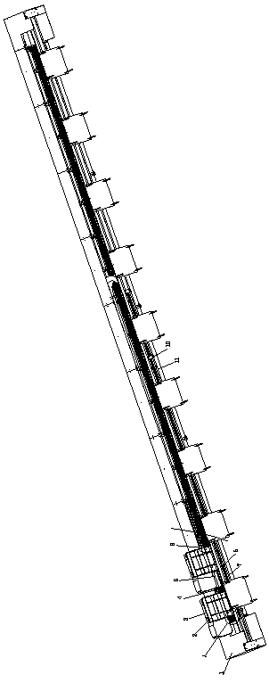
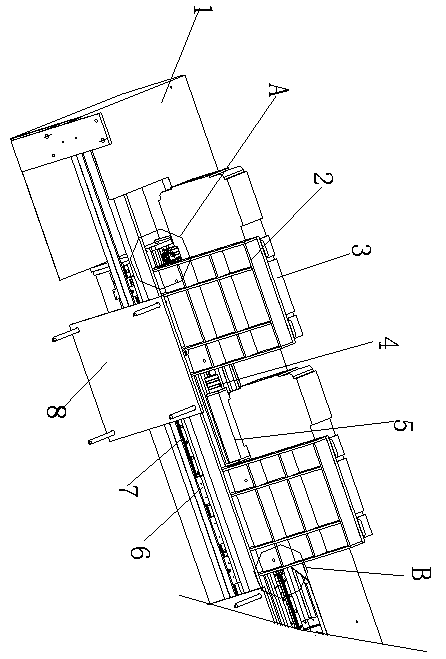
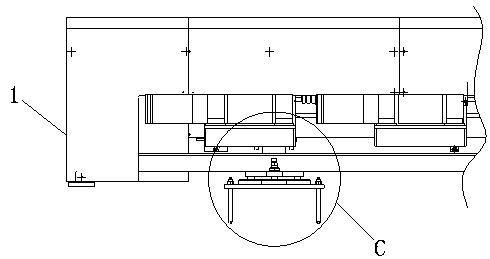
[0037] refer to Figure 1-Figure 8 with Figure 10, a robot walking shaft, comprising a dustproof housing 1, the left and right sides of the bottom of the dustproof housing 1 are fixedly connected with hollow squares 6 by bolts, the dustproof housing 1 includes gear one 16 and gear four 19, the gear A built-in pillar 14 is installed in the inner cavity of the first 16, and an opposite groove bar 17 is arranged on the outer wall of the first gear 16. The dustproof housing 1 has a built-in drive unit for driving the first 16 and the fourth 19 to rotate, and the gears The first 16 and the fourth gea...
PUM
 Abstract
Description
Claims
Application Information