Bridge vortex vibration control device

A control device, bridge technology, applied in bridges, bridge construction, bridge maintenance, etc., can solve problems such as vortex vibration

Inactive Publication Date: 2020-10-23
CHONGQING UNIV OF ARTS & SCI
View PDF0 Cites 1 Cited by
  • Summary
  • Abstract
  • Description
  • Claims
  • Application Information

AI Technical Summary

Problems solved by technology

[0004] In view of this, the object of the present invention is to provide a bridge vortex vibration control device to solve the technical problem that the bridge may appear vortex vibration under low wind speed conditions

Method used


Image

  • Bridge vortex vibration control device
  • Bridge vortex vibration control device
  • Bridge vortex vibration control device

Examples


Embodiment

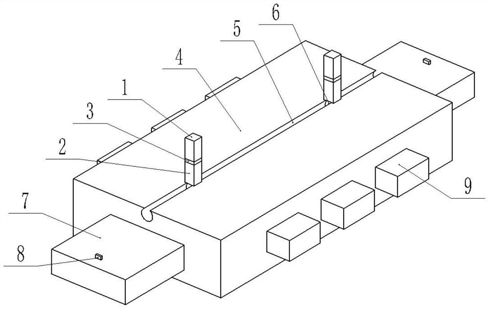
[0025] A bridge vortex vibration control device, combined with figure 1 , including a control unit and a mounting rod set at the bottom of the bridge.

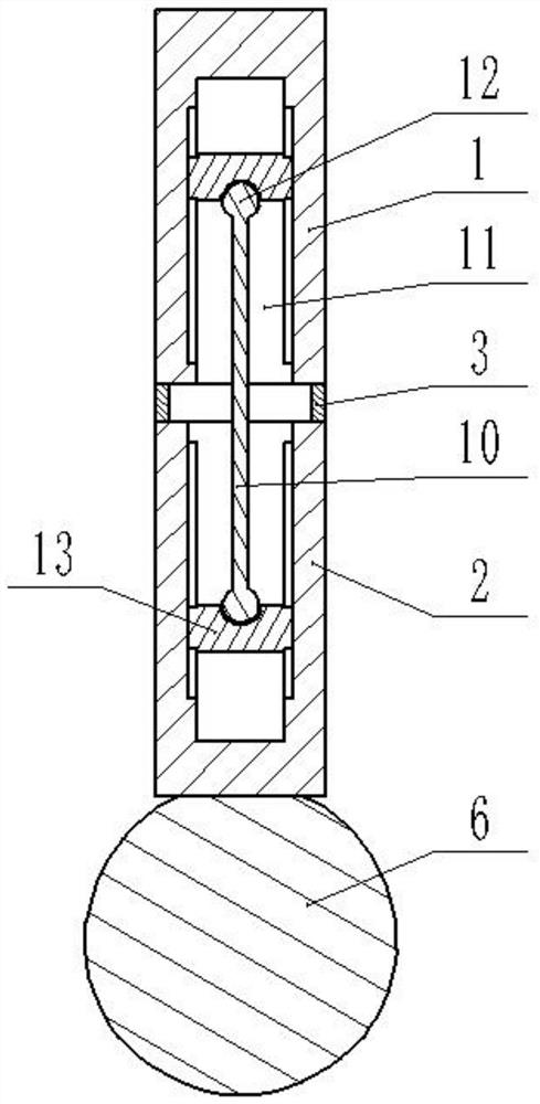
[0026] combine figure 2 , the installation pole includes an upper pole 1, a middle pole 10 and a lower pole 2, the cross sections of the upper pole 1, the middle pole 10 and the lower pole 2 are all square, and the bottom of the upper pole 1 and the top of the lower pole 2 are all provided with square The cavity 11 of the cavity 11 is vertically provided with vertical grooves on both sides of the inner wall of the cavity 11. The upper and lower ends of the vertical grooves do not penetrate the cavity 11. The vertical sliding connection in the vertical groove is connected with a ball hinge seat 13. The upper and lower sides of the middle rod 10 Both ends are integrally formed with a ball joint 12, and the ball joint 12 is connected with a ball joint seat 13. The upper rod 1 and the lower rod 2 are fixedly connected by a conn...


PUM


Abstract

The invention relates to the field of bridge engineering. The invention particularly discloses a bridge vortex vibration control device. The device comprises a control unit arranged at the bottom of abridge; the control unit comprises a plurality of controllers; the controller comprises a base and a plurality of sliding sheets; a sliding groove is formed in the base in the length direction; a wedge block is arranged in the sliding groove in a sliding mode; a plurality of sliding holes are formed in the two sides of the base; the sliding sheet is arranged in the sliding hole; a wedge surface matched with the wedge block is arranged at the end part of the sliding sheet; a wind shielding structure is arranged at the bottom of the sliding sheet; the wind shielding structure comprises a firstconnecting rod, a second connecting rod, a third connecting rod and a wind shielding curtain; the first connecting rod and the second connecting rod are hinged to the bottom of the sliding piece, thetwo ends of the third connecting rod are hinged to the first connecting rod and the second connecting rod respectively, the wind shielding curtain is quadrilateral, and three sides of the wind shielding curtain are arranged on the first connecting rod, the second connecting rod and the third connecting rod respectively. The technical problem that vortex vibration possibly occurs to a bridge underthe condition of low wind speed can be solved.

Description

technical field [0001] The invention relates to the field of bridge engineering, and specifically discloses a bridge vortex vibration control device. Background technique [0002] Vortex-induced vibration is a kind of wind-induced vibration phenomenon of long-span bridges under low wind speed. From the point of view of fluid, any non-streamlined object will alternately generate vortices on both sides of the object that are separated from the surface of the structure under a certain constant flow rate. Similar to the Karman vortex effect. [0003] The main structure of some bridges includes box girders. Box girders include top plates, bottom plates, webs, and several partitions. They are widely used due to their light weight and good rigidity. However, their aerodynamic performance is poor and they are prone to vortex-induced vibrations. Vortex-induced vibration can cause bridge shaking, driving difficulties, and even bridge damage. Contents of the invention [0004] In ...

Claims


Application Information

Patent Timeline
Patent Type & Authority Applications(China)
IPC IPC(8): E01D19/00
CPCE01D19/00E01D22/00F16F15/02
Inventor 王明振高霖黄宜婧
Owner CHONGQING UNIV OF ARTS & SCI
Why Eureka
Try Eureka