Agricultural mechanical pesticide spraying machine pesticide liquid mixing device based on fluid mechanics

A technology of agricultural machinery and fluid mechanics, applied in spraying devices, devices for catching or killing insects, animal husbandry, etc., can solve problems such as failure to achieve the original intention of use, poor applicability of spraying machines, and reduced drug effects

Pending Publication Date: 2021-05-28
龙利和
View PDF7 Cites 0 Cited by
  • Summary
  • Abstract
  • Description
  • Claims
  • Application Information

AI Technical Summary

Problems solved by technology

[0003] 1. In the prior art, during the use of the sprayer, there is a problem that the drug is mixed unevenly, causing the drug to precipitate, resulting in insufficient drug dosage, and reducing the effect of the drug;
[0004] 2. In the existing technology, for some farmlands, the growth of crops will be affected, and the original intention of high-efficiency use will not be achieved. The applicability of the sprayer will become poor, so structural innovation is required to solve specific problems

Method used


Image

  • Agricultural mechanical pesticide spraying machine pesticide liquid mixing device based on fluid mechanics
  • Agricultural mechanical pesticide spraying machine pesticide liquid mixing device based on fluid mechanics
  • Agricultural mechanical pesticide spraying machine pesticide liquid mixing device based on fluid mechanics

Examples


Embodiment 1

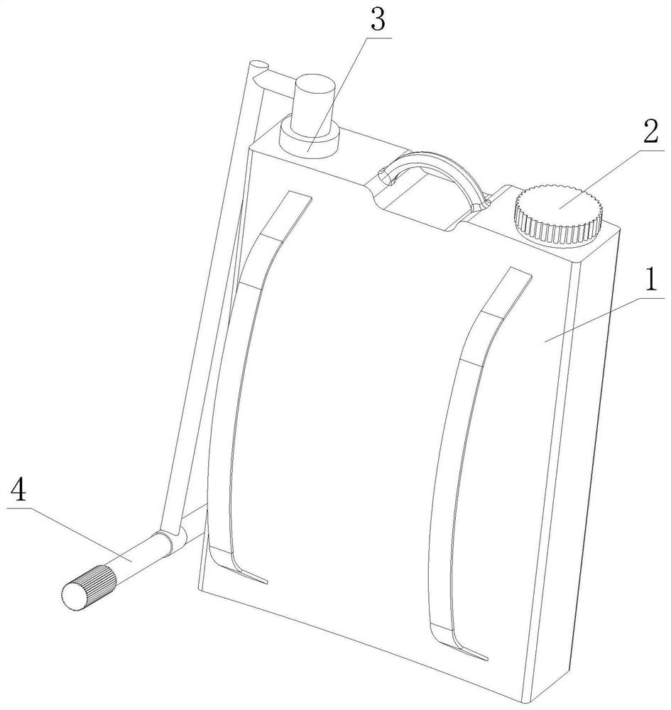
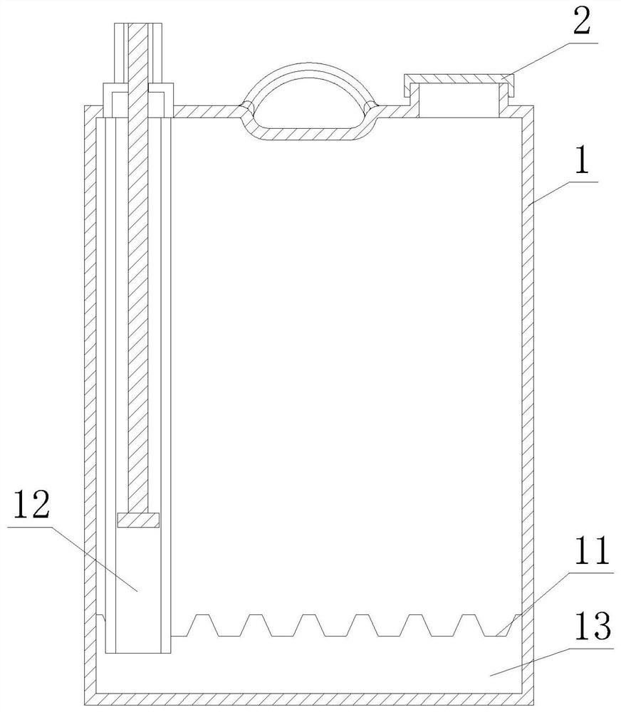
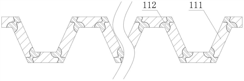
[0024] Such as figure 1 - image 3 As shown, the present invention provides a liquid medicine mixing device for an agricultural machinery spraying machine based on fluid mechanics, comprising a casing 1, the two sides of the upper end of the casing 1 are respectively provided with a liquid inlet 2 and a pressure chamber 3, and the casing 1 is close to the pressure chamber. The bottom of one side of the chamber 3 is movably connected with a pressure rod 4, and the inner middle part of the cabinet 1 is provided with a mixing plate 11, and the inside of the cabinet 1 is located at the bottom of the pressure chamber 3 and is provided with a discharge channel 12. A liquid retention chamber 13 is arranged below, and the discharge channel 12 is connected to the liquid retention chamber 13 . The inside of the mixing plate 11 is provided with a partition 111 , and the corners of the partition 111 are provided with a liquid mixing structure 112 .

[0025] In this embodiment, the partit...

Embodiment 2

[0027] Such as Figure 4 As shown, on the basis of Embodiment 1, the present invention provides a technical solution: both sides of the side wall of the partition 111 are fixedly connected with a spoiler a4, and a liquid flow channel a1 is arranged inside the liquid mixing structure 112, and the liquid Both ends of the flow channel a1 are movably connected with a mixing wheel a3, and the middle part of the liquid flow channel a1 is fixedly connected with a spoiler grid a2, and the mixing wheel a3 inside the corner of the partition 111 is a part far away from the spoiler a4. Installed on the side, the mixing wheel a3 outside the corner of the partition 111 is installed on the side close to the spoiler a4, and the inclined setting of the mixing wheel a3 makes the flow of water and air flow gather at the side of the mixing wheel a3 One side, so that the mixing wheel a3 is easier to rotate, so as to guide the flow direction of the water flow.

[0028] In this embodiment, through ...

Embodiment 3

[0030] Such as Figure 5 As shown, on the basis of Embodiment 2, the present invention provides a technical solution: preferably, the inside of the mixing wheel a3 is provided with a central axis s1, and both ends of the central axis s1 are fixedly connected with side plates s4, and the central axis The outer surface of s1 is fixedly connected with a support rod s2, and the end of each adjacent two support rods s2 away from the central axis s1 is fixedly connected with a meniscus s3, and there is a gap between the central axis s1, support rod s2, and meniscus s3. The cavity s5 is provided with an eccentric ball s6 inside the cavity s5, and the central axis s1, the support rod s2, and the meniscus s3 are designed in an integrated manner.

[0031] In this embodiment, the setting of the meniscus s3 is used to increase the impact force on the surface of the meniscus s3 when the fluid passes through, thereby promoting the rotation of the mixing wheel a3. When a3 rotates, the cente...


PUM


Abstract

The invention discloses an agricultural mechanical pesticide spraying machine pesticide liquid mixing device based on fluid mechanics, and relates to the technical field of agricultural machinery. The agricultural mechanical pesticide spraying machine pesticide liquid mixing device comprises a case, a liquid inlet and a pressure cavity are correspondingly formed in two sides of the upper end of the case, a pressing rod is movably connected to the lower part of one side, close to the pressure cavity, of the case, and a material mixing plate is arranged below the middle part in the case. Through combination of a liquid flow channel, a turbulent flow grid and a material mixing wheel, the material mixing wheel is conveniently rotated through flowing of fluid when the pesticide spraying machine pressurizes and sprays; a turbulent flow effect is achieved when a solution passes through the cambered surface of the material mixing wheel; and by arranging an eccentric ball, when the material mixing wheel rotates, the material mixing wheel impacts a meniscus to generate vibration, so that undissolved and coagulated blocky pesticide in the solution is vibrated and scattered, the pesticide is mixed with water, when the solution passes through the turbulent flow grid, turbulent flow is generated, the pesticide is further mixed with water, and the situation that the pesticide cannot be completely sprayed into a farmland due to pesticide precipitation when the pesticide is sprayed is avoided.

Description

technical field [0001] The invention relates to a spraying machine, relates to the technical field of agricultural machinery, in particular to a liquid medicine mixing device for an agricultural machinery spraying machine based on fluid mechanics. Background technique [0002] A spraying machine is a kind of agricultural machinery that mixes water and medicinal liquid and sprays the liquid onto the surface of objects through pressure. It is a kind of agricultural pesticide application machinery. There are following problems at prior art: [0003] 1. In the prior art, during the use of the sprayer, there is a problem that the drug is mixed unevenly, causing the drug to precipitate, resulting in insufficient drug dosage, and reducing the effect of the drug; [0004] 2. In the prior art, for some farmlands, the growth of crops will be affected, and the original intention of high-efficiency use cannot be achieved. The applicability of the sprayer becomes poor, so structural inn...

Claims


Application Information

Patent Timeline
Patent Type & Authority Applications(China)
IPC IPC(8): A01M7/00A01G13/00B05B15/25
CPCA01M7/0042A01G13/00B05B15/25
Inventor 龙利和
Owner 龙利和
Why Eureka
Try Eureka