
Mounting system of steel truss girder bridge

An installation system and a technology for steel trusses, applied in the field of bridge construction, can solve the problems of construction space restriction, long construction period, affecting bridge construction accuracy and connection quality, etc.

Pending Publication Date: 2020-10-23
ROAD & BRIDGE SOUTH CHINA EINGINEERING CO LTD +1
View PDF0 Cites 1 Cited by
  • Summary
  • Abstract
  • Description
  • Claims
  • Application Information

AI Technical Summary

Problems solved by technology

When the segmental cantilever is constructed by assembly, the construction period is relatively long, and there are many assembly procedures on site, which affects the construction accuracy and connection quality of the bridge
For girder bridges with large spans, the construction of the bridge using the jacking construction method requires auxiliary piers to be set up section by section, which affects the navigation or traffic within the span range, which greatly restricts the construction space and increases the construction workload. Pushing construction has a certain influence on the line shape of the bridge and the stress of the beam body during the construction stage, which is unfavorable to the stress of the bridge structure

Method used


Image

  • Mounting system of steel truss girder bridge
  • Mounting system of steel truss girder bridge
  • Mounting system of steel truss girder bridge

Examples


Embodiment Construction

[0031] Embodiments of the present invention are described in detail below, and examples of the embodiments are shown in the drawings, wherein the same or similar reference numerals denote the same or similar elements or elements having the same or similar functions throughout. The embodiments described below by referring to the figures are exemplary only for explaining the present invention and should not be construed as limiting the present invention.

[0032] Those skilled in the art will understand that unless otherwise stated, the singular forms "a", "an", "said" and "the" used herein may also include plural forms. It should be further understood that the word "comprising" used in the description of the present invention refers to the presence of features, integers, steps, and operations, but does not exclude the existence or addition of one or more other features, integers, steps, and operations.

[0033] Those skilled in the art can understand that, unless otherwise defi...


PUM


Abstract

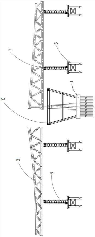
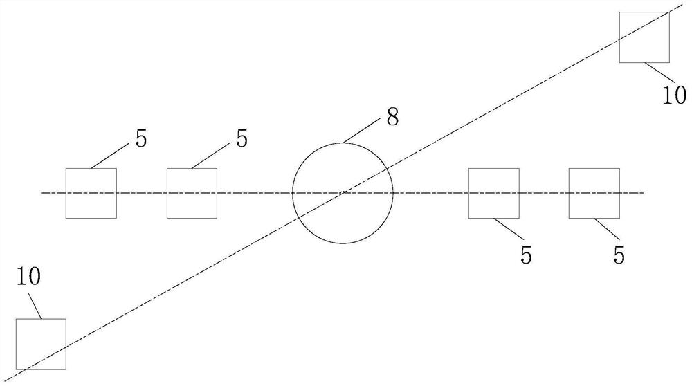
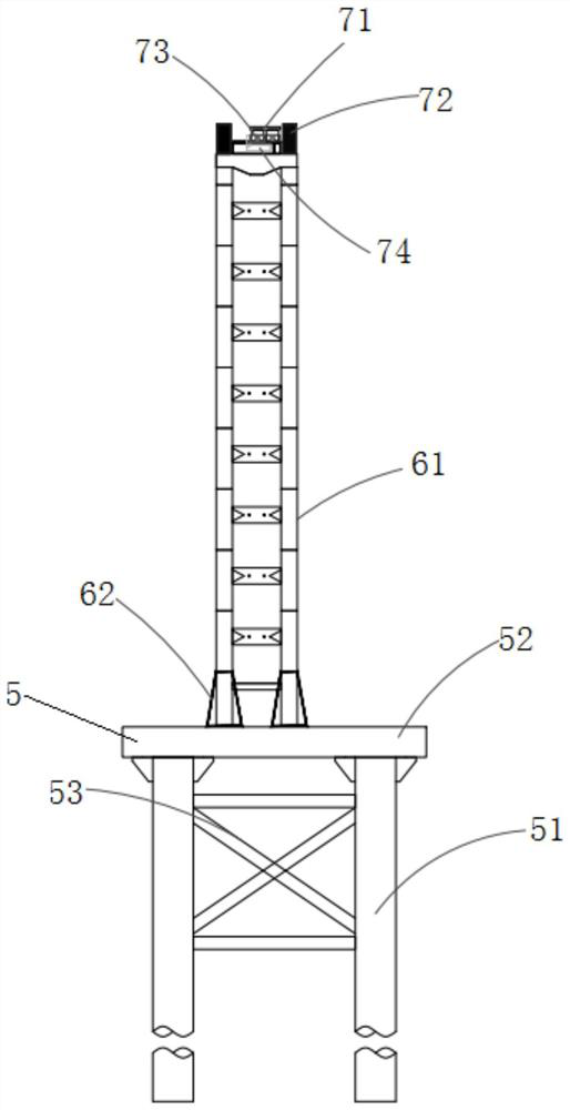
The invention relates to a mounting system of a steel truss girder bridge. The system comprises a temporary buttress mechanism, a horizontal rotating disc mechanism and a locking pier structure; the temporary buttress mechanism used for placing small sections of steel beams and pushing the small sections of steel beams to a preset position on the top of a main pier, so that two small sections of steel beams are folded to obtain a large section of steel beams; the horizontal rotating disc mechanism comprises a horizontal rotating disc which is arranged on the top of the main pier and is used for horizontally rotating the large section of the steel beam to a preset position; and the locking pier structure is provided with a locking structure for locking the side span end of the large sectionof the steel beam at the preset position. The steel beam large section is prefabricated in a factory, the construction quality of the steel beam large section is guaranteed, influence of a field construction process on stress of a main beam structure is reduced, and overall installation of the steel beam large section is achieved. Meanwhile, by arranging the temporary buttress mechanism and the locking pier structure, occupation of roads and channels under the bridge is avoided, and passage of the roads and the channels under the bridge is not hindered in the bridge construction process.

Description

technical field [0001] The invention relates to the technical field of bridge construction, in particular to an installation system of a steel truss girder bridge. Background technique [0002] Steel truss girder bridges use steel trusses as the main load-bearing structure of girder bridges. Generally, the space structure is composed of two main trusses, longitudinal connecting systems and horizontal connecting systems. In the prior art, conventional construction techniques for the main girder of long-span steel truss girder bridges are usually constructed by segmental cantilever assembly or jacking methods. When the segmental cantilever is constructed by assembly, the construction period is relatively long, and there are many assembly processes on site, which affects the construction accuracy and connection quality of the bridge. For girder bridges with large spans, the construction of the bridge using the jacking construction method requires auxiliary piers to be set up s...

Claims


Application Information

Patent Timeline
Patent Type & Authority Applications(China)
IPC IPC(8): E01D21/00
CPCE01D21/00
Inventor 王斌卢冠楠肖向荣黄开开徐勇张皎刘怀刚高世强王金梁向韬
Owner ROAD & BRIDGE SOUTH CHINA EINGINEERING CO LTD
Learn More