
Power transmission tower used on the basis of electric power transmission

A transmission tower and power transmission technology, which is applied in the installation of cables, suspension devices of cables, towers, etc., can solve the problems of electric shock death of high-voltage lines and difficulty in wire installation.

Inactive Publication Date: 2020-10-23
胡晓霖
View PDF7 Cites 2 Cited by
  • Summary
  • Abstract
  • Description
  • Claims
  • Application Information

AI Technical Summary

Problems solved by technology

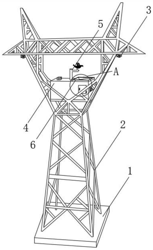
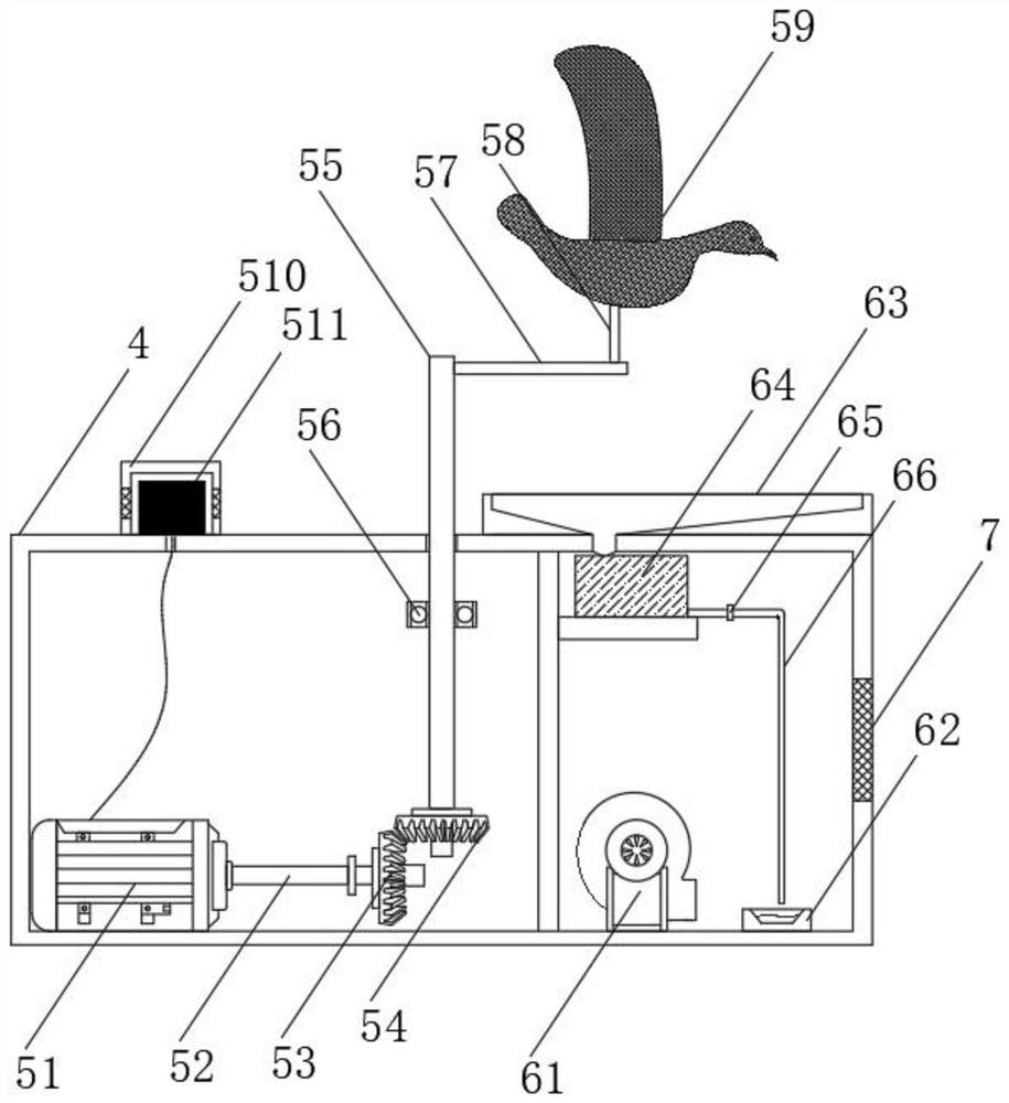
[0005] Aiming at the deficiencies of the prior art, the present invention provides a power transmission tower based on power transmission, with the anti-skid structure on the top of the extruded plate, the wire connector can be more firmly fixed between the outer frame and the extruded plate without sliding , through the natural fear of common birds to raptors, nearby birds can be expelled visually and aurally, and the smell of raptor feces can be emitted faster and cover a wider range, so that the area covered Birds dare not stay on the wires and other advantages, which solves the problem that when the staff of the traditional transmission tower based on power transmission install the transmission line, due to the high tower, when the two ends of the wires are docked, it is difficult to fix the two wires at the same time, resulting in It is difficult to install wires. There are often birds nesting on the transmission tower, and the high-voltage lines next to the transmission tower often have the problem of birds stopping and getting electrocuted.

Method used


Image

  • Power transmission tower used on the basis of electric power transmission
  • Power transmission tower used on the basis of electric power transmission
  • Power transmission tower used on the basis of electric power transmission

Examples


Embodiment Construction

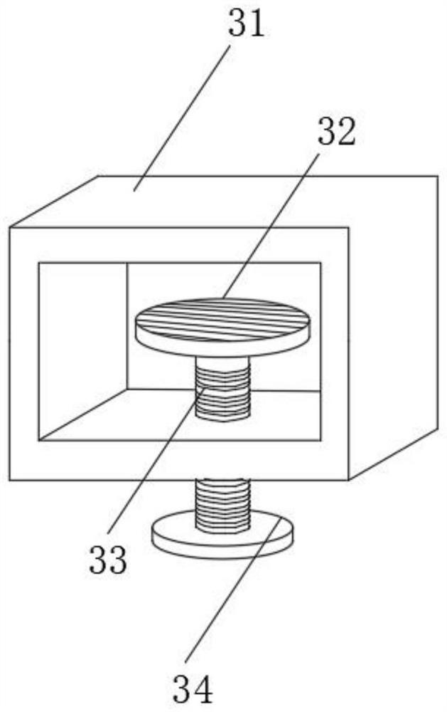
[0028] The following will clearly and completely describe the technical solutions in the embodiments of the present invention with reference to the accompanying drawings in the embodiments of the present invention. Obviously, the described embodiments are only some, not all, embodiments of the present invention. Based on the embodiments of the present invention, all other embodiments obtained by persons of ordinary skill in the art without making creative efforts belong to the protection scope of the present invention.

[0029] see Figure 1-5, a power transmission tower based on power transmission, comprising a base 1, characterized in that: the upper end of the base 1 is fixedly connected with a tower main body 2, and a clamping mechanism 3 is provided on both sides of the upper end of the iron tower main body 2, and the clamping mechanism 3 includes an outer Frame 31, the bottom of outer frame 31 is provided with threaded mandrel 33, the upper end of threaded mandrel 33 is ...


PUM


Abstract

The invention relates to the technical field of electric power transmission and discloses a power transmission tower used on the basis of electric power transmission. The power transmission tower usedon the basis of electric power transmission comprises a base; a tower main body is fixedly connected to the upper end of the base; clamping mechanisms are arranged on the two sides of the upper end of the tower main body; the clamping mechanisms comprise external frames; lead screws are arranged to run through the bottoms of the external frames; extruding plates are fixedly connected to the upperends of the lead screws; rotating discs are fixedly connected to the lower ends of the lead screws; and a protecting box is fixedly connected to the upper side of the interior of the tower main body.According to the power transmission tower used on the basis of electric power transmission, through skidproof grain structures at the upper ends of the extruding plates, electric wire connectors canbe more stably fixed between the external frames and the extruding plates to be unable to slide; and moreover, through natural fears of common birds to birds of prey, the nearby birds can be driven atvisual and aural levels, odour of faeces of the birds of prey can more rapidly emit to a wider range; and therefore, the birds in a coverage area do not dare to stay on electric wires.

Description

technical field [0001] The invention relates to the technical field of power transmission, in particular to a power transmission tower used based on power transmission. Background technique [0002] The transmission tower is the support point of the overhead line. One circuit is erected on the transmission tower, which is a single-circuit transmission tower, and two circuits are erected on the transmission tower, which is a double-circuit transmission tower. A single circuit refers to a circuit in which a load has one power supply; a double circuit refers to a circuit in which a load has two power supplies. Generally, enterprises that require high reliability of power supply, or important substations in the region, use double-circuit power supply, which can protect one power supply from power failure for some reason, and the other power supply can continue to supply power. However, for general power supply reliability requirements are not High small and medium-sized users o...

Claims


Application Information

Patent Timeline
Patent Type & Authority Applications(China)
IPC IPC(8): E04H12/10E04H12/18H02G7/00H02G7/05A01M29/06A01M29/16A01M29/12
CPCA01M29/06A01M29/12A01M29/16E04H12/10E04H12/182H02G7/00H02G7/053
Inventor 胡晓霖
Owner 胡晓霖
Learn More