
Fixing frame for electromechanical equipment and installation method thereof

An installation method and technology of electromechanical equipment, applied in the direction of mechanical equipment, machine platform/bracket, supporting machine, etc., can solve the problems of large spring loss and poor shock absorption effect, and achieve vibration reduction, good cushioning effect, and good shock absorption effect Effect

Active Publication Date: 2021-04-13
SHANDONG CHENXIN NEW ENERGY
View PDF12 Cites 0 Cited by
  • Summary
  • Abstract
  • Description
  • Claims
  • Application Information

AI Technical Summary

Problems solved by technology

[0005] The purpose of the present invention is to solve the shortcomings of poor shock absorption effect of electromechanical equipment in the prior art, large spring loss, and the need for regular replacement and maintenance, and propose a fixed frame for electromechanical equipment and its installation method

Method used


Image

  • Fixing frame for electromechanical equipment and installation method thereof
  • Fixing frame for electromechanical equipment and installation method thereof
  • Fixing frame for electromechanical equipment and installation method thereof

Examples


Embodiment 1

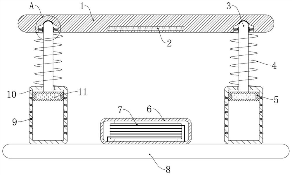
[0032] refer to Figure 1-3 , a method for installing a fixing frame for electromechanical equipment, the specific steps are as follows:

[0033] S1: Fix the protective box 6 and the two vertical cylinders 10 on the bottom plate 8 by bolts;

[0034] S2: Fix the magnetic block 11 to the bottom end of the support rod 3 and put the anti-wear sleeve 5 on the magnetic block 11, and then put the two magnetic blocks 11 into the two vertical tubes 10 respectively;

[0035] S3: welding one end of the first spring 4 to the upper surface of the vertical cylinder 10, and welding the other end to the upper side wall of the support rod 3;

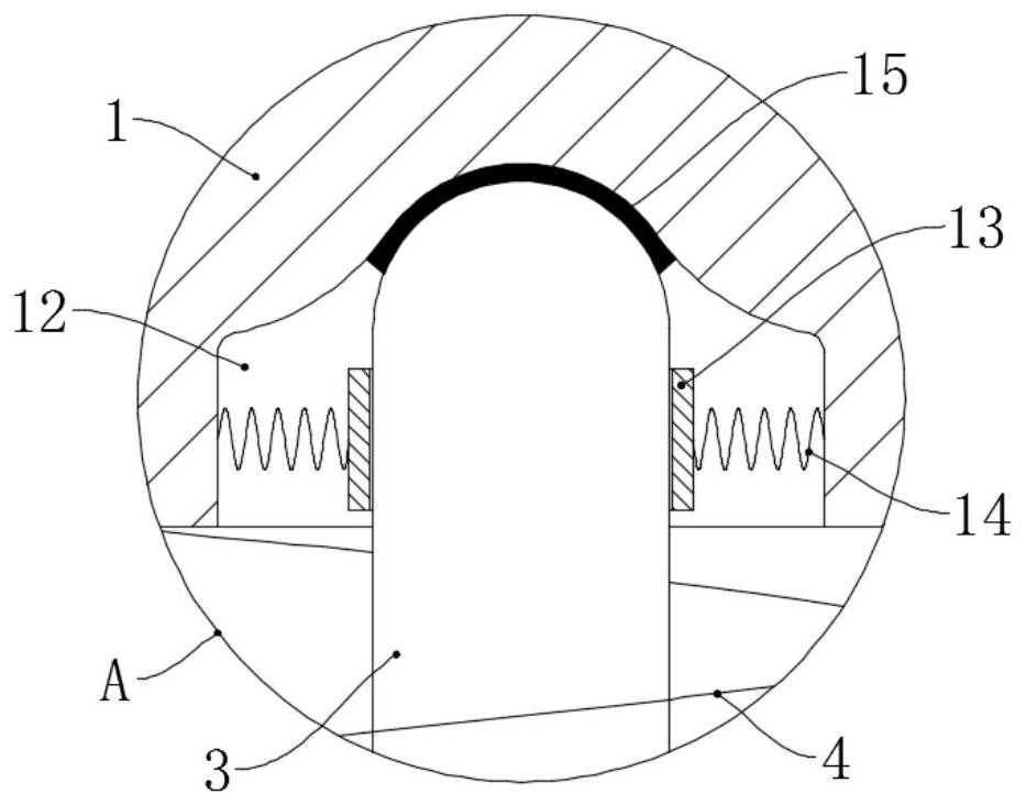
[0036] S4: welding a plurality of second springs 14 with arc-shaped plates 13 symmetrically in the two assembly grooves 12 and fixing the buffer member 2 under the stage 1;

[0037] S5: Make the two support rods 3 stably support the stage 1 through the assembly groove 12, and the arc-shaped plate 13 in the same assembly groove 12 is offset against the ...

Embodiment 2

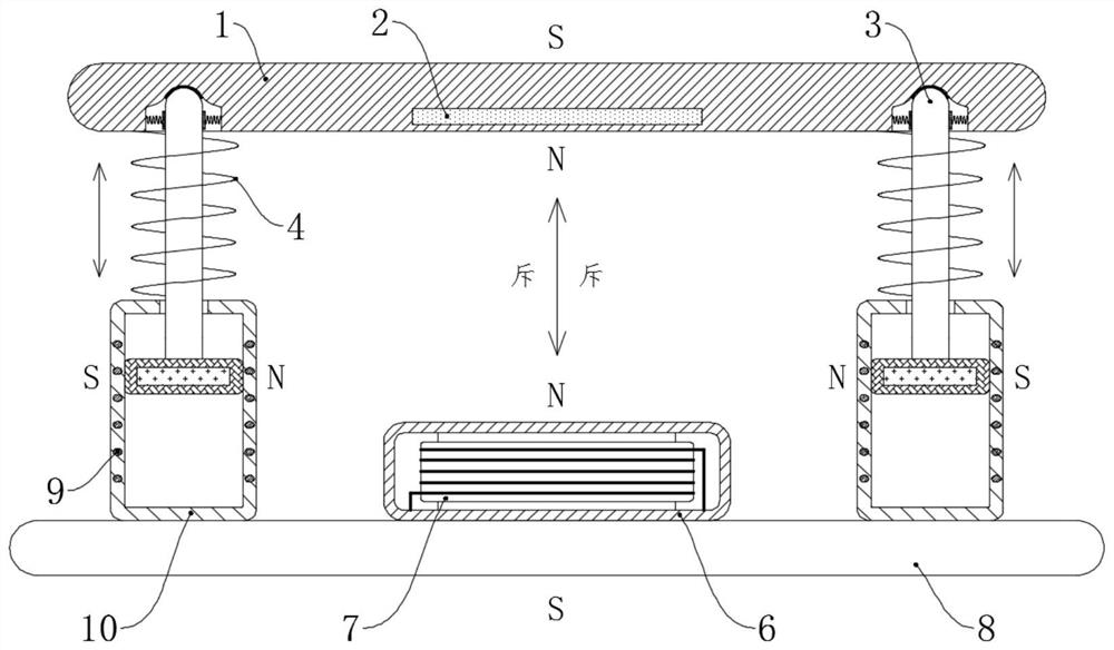
[0048] refer to Figure 4-6 The difference between this embodiment and Embodiment 1 is that: a chute 16 is provided in the stage 1, and the buffer member 2 is movably placed in the chute 16, and the buffer member 2 includes two permanent magnet plates with the same polarity direction. The side wall of the chute 16 is bonded with a circle of buffer sheet 17 in the circumferential direction, and the middle part of the chute 16 divides the internal space of the chute 16 into two parts by the buffer sheet 17. Two permanent magnet plates are respectively located on the two sides of the buffer sheet 17 On the other hand, the buffer sheet 17 can avoid the damage or demagnetization of the permanent magnet plate caused by the rigid collision between the buffer member 2 and the chute 16 .

[0049] During specific work, when the electromechanical equipment is subjected to vibration in the horizontal direction, the second spring 14 and the rubber gasket 15 still have the effect of weakeni...


PUM


Abstract

The invention discloses a fixing frame for electromechanical equipment and an installation method thereof, which mainly includes the following steps: S1, installing a protective box and a vertical cylinder; S2, fixing a magnetic block and a support rod; S3, welding the first spring; S4, welding the second Spring and fix the buffer; S5, assembling the stage; S6, connecting the circuit, a kind of mechanical and electrical equipment fixing frame is also involved in the installation process, including the stage and the bottom plate, and the bottom plate is fixed with the protective box and the bottom plate by bolts. Two vertical cylinders, and the two vertical cylinders are symmetrically distributed on both sides of the protective box, coils are wound in the side walls of each vertical cylinder, and a wear-resistant belt is slidably installed in each vertical cylinder Set of magnetic blocks. The invention weakens the vibration through the interaction of the magnetic field, which not only has a better shock absorption effect, but also reduces the accumulation of fatigue damage of the spring, making the service life longer, and the stronger the vibration of the electromechanical equipment, the stronger the repulsion force of the buffer is. Larger, the cushioning effect will be better.

Description

technical field [0001] The invention relates to the technical field of electromechanical equipment, in particular to a fixing frame for electromechanical equipment and an installation method thereof. Background technique [0002] Electromechanical equipment usually refers to equipment that applies mechanical and electronic technologies. Whether it is in the information field, people's livelihood, industry, or power field, a large number of electromechanical equipment will be used. In order to reduce the vibration of electromechanical equipment and avoid strong vibrations on the internal parts of the equipment If damage is caused, a shock-absorbing pad is often placed under the electromechanical equipment. [0003] Although the common shock absorbing pad has a certain shock absorbing effect, the shock absorbing effect is relatively poor, and it cannot effectively buffer relatively strong shocks, and the shock buffering effect in the horizontal direction is not obvious. propo...

Claims


Application Information

Patent Timeline
Patent Type & Authority Patents(China)
IPC IPC(8): F16F15/03F16F15/08F16M11/00
CPCF16F15/03F16F15/085F16F2222/06F16M11/00
Inventor 刘巍巍
Owner SHANDONG CHENXIN NEW ENERGY
Learn More