Improved faucet

An improved faucet technology, applied in the faucet field, can solve the problems of space limitation, complicated process and high cost

Pending Publication Date: 2020-10-23
福建盛辉科技发展有限公司 +1
View PDF0 Cites 0 Cited by
  • Summary
  • Abstract
  • Description
  • Claims
  • Application Information

AI Technical Summary

Problems solved by technology

Due to the limitation of the position of the water outlet on the inner core 200, the position in the height direction of the part where the water outlet pipe 120 of the existing faucet is connected to the shell main body 110 is relatively low, resulting in the li

Method used


Image

  • Improved faucet
  • Improved faucet
  • Improved faucet

Examples


Embodiment approach

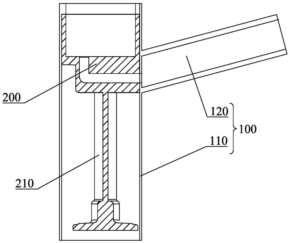
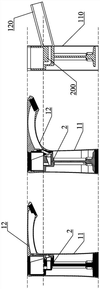
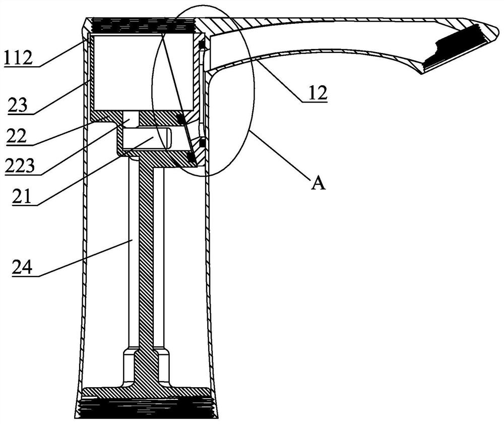
[0061] Preferably, as the second embodiment of the present invention, a limiting protrusion 33 is provided on the surface of the waterway lifting piece 3 abutting against the shell main body 11, and the water outlet end 312 of the lifting channel 31 is set at the limiting position. On the protrusion 33 ; on the inner wall of the housing body 11 is formed a limiting groove 116 that cooperates with the limiting protrusion 33 , and the limiting protrusion 33 is embedded in the limiting groove 116 . The waterway lifting piece 3 is preliminarily connected to the inner wall of the housing main body 11 through the limiting protrusion 33 , which facilitates the subsequent sealing connection between the valve core seat 2 and the waterway lifting piece 3 .

[0062] Compared with the second embodiment of the waterway lifting piece 3, the first embodiment of the waterway lifting piece 3 has the characteristics of convenient processing and low requirements on processing accuracy.

[0063] ...


PUM


Abstract

The invention discloses an improved faucet. The improved faucet comprises a shell, a valve element seat and a water path lifting sheet, wherein the shell comprises a shell main body and a water outletpipe communicating with the shell main body; a lifting channel is formed in the water path lifting sheet and provided with a water inlet end and a water outlet end, and the water outlet end is higherthan the water inlet end in the vertical direction; the valve element seat is provided with a mixed water outlet hole, and the mixed water outlet hole abuts against and is connected to the water pathlifting sheet in a sealed mode and communicates with the water inlet end of the lifting channel; and the face, far away from the valve element seat, of the water path lifting sheet abuts against theinner wall of the shell main body in a sealed mode, and the communicating position between the water outlet pipe and the water outlet end is higher than the height where the water inlet end is locatedin the vertical direction. Compared with the prior art, according to the improved faucet, by arranging the lifting channel, water flow of the mixed water outlet hole originally located below a valveelement is lifted so that the position of the water outlet pipe on the shell main body can be lifted, and the use space below the water outlet pipe is enlarged.

Description

technical field [0001] The invention relates to the field of faucets, in particular to an improved faucet. Background technique [0002] Such as figure 1 with figure 2 As shown, the structure of the existing faucet includes a casing 100 , an inner core 200 and a valve core, and the casing includes a casing body 110 and a water outlet pipe 120 integrally connected to the casing body 110 . The lower end of the inner core is connected with a hot and cold water pipe 210, and the upper end surface of the inner core is formed with a cold water outlet and a hot water outlet. After being mixed by the valve core, the cold and hot water are discharged through the water outlet on the inner core 200 located below the valve core. And the water is discharged through the water outlet pipe 120 on the casing. Due to the limitation of the position of the water outlet on the inner core 200, the position in the height direction of the part where the water outlet pipe 120 of the existing fau...

Claims


Application Information

Patent Timeline
IPC IPC(8): F16K11/074F16K27/04F16K3/30
CPCF16K3/30F16K11/0743F16K27/045
Inventor 钟圣辉周石长
Owner 福建盛辉科技发展有限公司
Why Eureka
Try Eureka