Ultrasonic probe bandwidth detection method and system based on lens echoes

An ultrasonic probe and bandwidth detection technology, which is applied in radio wave measurement systems, ultrasonic/sonic/infrasonic equipment testing/calibration, ultrasonic/sonic/infrasonic diagnosis, etc., can solve the problem of not truly reflecting the bandwidth characteristics of ultrasonic probes and limiting ultrasonic probes Optimal design and other issues

Active Publication Date: 2020-10-23
聚融医疗科技(杭州)有限公司
View PDF5 Cites 2 Cited by
  • Summary
  • Abstract
  • Description
  • Claims
  • Application Information

AI Technical Summary

Problems solved by technology

This method is limited by the acoustic axis alignment accuracy and the influence of acoustic nonlinearity, and cannot truly reflect the bandwidth characteristics of the ultrasonic probe, which limits the optimal design of the ultrasonic probe.

Method used


Image

  • Ultrasonic probe bandwidth detection method and system based on lens echoes
  • Ultrasonic probe bandwidth detection method and system based on lens echoes
  • Ultrasonic probe bandwidth detection method and system based on lens echoes

Examples


Embodiment 1

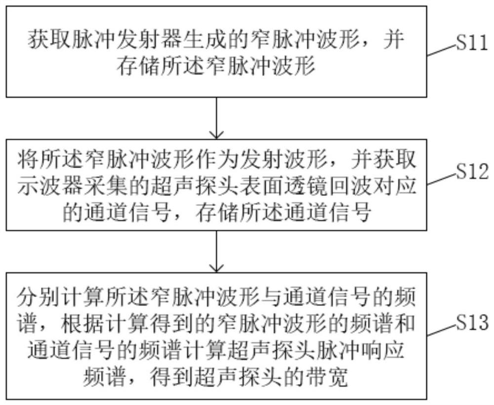
[0050] A method for detecting the bandwidth of an ultrasonic probe based on lens echo provided in this embodiment, such as figure 1 shown, including steps:

[0051] S11. Obtain the narrow pulse waveform generated by the pulse transmitter, and store the narrow pulse waveform;

[0052] S12. Using the narrow pulse waveform as the transmitting waveform, and obtaining the channel signal corresponding to the lens echo of the ultrasonic probe surface collected by the oscilloscope, and storing the channel signal;

[0053] S13. Calculate the spectrum of the narrow pulse waveform and the channel signal respectively, calculate the pulse response spectrum of the ultrasonic probe according to the calculated spectrum of the narrow pulse waveform and the spectrum of the channel signal, and obtain the bandwidth of the ultrasonic probe.

[0054] It should be noted that the execution subject of this embodiment is the detection system.

[0055] In step S11, the narrow pulse waveform generated ...

Embodiment 2

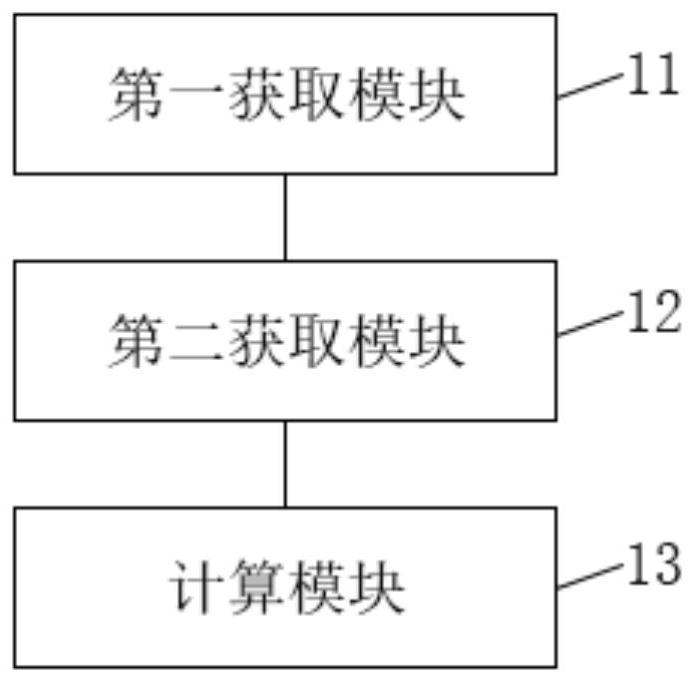
[0091] This embodiment provides a system for detecting the bandwidth of an ultrasonic probe based on lens echo, such as image 3 shown, including:

[0092] The first obtaining module 11 is used to obtain the narrow pulse waveform generated by the pulse transmitter, and store the narrow pulse waveform;

[0093] The second acquisition module 12 is configured to use the narrow pulse waveform as a transmission waveform, and acquire a channel signal corresponding to the ultrasonic probe surface lens echo collected by an oscilloscope, and store the channel signal;

[0094] The calculation module 13 is used to calculate the spectrum of the narrow pulse waveform and the channel signal respectively, calculate the pulse response spectrum of the ultrasonic probe according to the calculated spectrum of the narrow pulse waveform and the spectrum of the channel signal, and obtain the bandwidth of the ultrasonic probe.

[0095] Further, the channel signal corresponding to the lens echo on t...


PUM


Abstract

The invention discloses an ultrasonic probe bandwidth detection method and system based on lens echo. The method comprises steps of S11, obtaining a narrow pulse waveform generated by a pulse emitter,and storing the narrow pulse waveform; S12, taking the narrow pulse waveform as a transmitted waveform, acquiring a channel signal corresponding to an ultrasonic probe surface lens echo acquired by an oscilloscope, and storing the channel signal; and S13, respectively calculating the frequency spectrums of the narrow pulse waveform and the channel signal, and calculating the pulse response frequency spectrum of the ultrasonic probe according to the calculated frequency spectrums of the narrow pulse waveform and the channel signal to obtain the bandwidth of the ultrasonic probe. The method isadvantaged in that lens echoes generated by mismatching of the probe lens and the air acoustic impedance are used for detecting the bandwidth of the ultrasonic probe, precision of bandwidth measurement of the ultrasonic probe is improved, and complexity of bandwidth measurement of the ultrasonic probe is reduced.

Description

technical field [0001] The invention relates to the technical field of ultrasonic probe detection, in particular to a method and system for detecting the bandwidth of an ultrasonic probe based on lens echo. Background technique [0002] An ultrasonic probe is a device that emits and receives ultrasonic waves during ultrasonic testing. The performance of the probe directly affects the characteristics of the ultrasonic wave and affects the detection performance of the ultrasonic wave. [0003] However, in an ultrasound system, the bandwidth determines the image quality of ultrasound harmonic imaging and contrast-enhanced ultrasound imaging, and the bandwidth of the ultrasound probe determines the bandwidth of the ultrasound system. The current measurement of the bandwidth of the ultrasonic probe is mainly obtained by reflecting the target echo in water. This method is limited by the accuracy of the alignment of the acoustic axis and the influence of acoustic nonlinearity, an...

Claims


Application Information

Patent Timeline
Patent Type & Authority Applications(China)
IPC IPC(8): G01S7/52A61B8/00
CPCG01S7/52004A61B8/58
Inventor 吴宇鹏冯巧梅
Owner 聚融医疗科技(杭州)有限公司
Why Eureka
Try Eureka