
Touch module and intelligent terminal

A touch module and touch technology, applied in character and pattern recognition, instruments, electrical components, etc., can solve problems such as difficult full-screen fingerprint recognition

Pending Publication Date: 2020-10-23
NANCHANG OUFEI BIOLOGICAL IDENTIFICATION TECH
View PDF0 Cites 5 Cited by
  • Summary
  • Abstract
  • Description
  • Claims
  • Application Information

AI Technical Summary

Problems solved by technology

[0004] Based on this, it is necessary to provide a touch module and an intelligent terminal for the problem that it is difficult to realize full-screen fingerprint recognition in the above touch module.

Method used


Image

  • Touch module and intelligent terminal
  • Touch module and intelligent terminal
  • Touch module and intelligent terminal

Examples


Embodiment 1

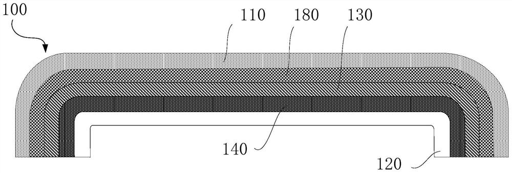
[0045] Such as figure 1 , figure 2 , image 3 , Figure 4 as well as Figure 5 As shown, the present invention provides a touch module 100, the touch module 100 includes a cover plate 110, a display layer 120, a piezoelectric layer 130 and a touch control layer stacked between the cover plate 110 and the display layer 120. Layer 140, where:

[0046] The cover plate 110 can completely cover other structural components. The cover plate 110 can be made of a transparent material, and the cover plate 110 can be selected from a material with an acoustic impedance close to that of the display layer 120, such as any material such as a glass plate, a stone substrate or a plastic film. A layer structure that can come into contact with a touch object (such as a user's finger);

[0047] The touch layer 140 includes a touch IC142 and at least one TFT electrode layer 141 electrically connected to the touch IC142. The TFT electrode layer 141 is used to form an inductive capacitance and...

Embodiment 2

[0075] In addition, the present invention also provides a smart terminal, including the touch module 100 according to any one of the above technical solutions and a casing, and the touch module 100 is disposed on the casing. In specific settings, the display device in the present invention can be used in various smart terminals, such as smart phones, smart bracelets, notebook computers, tablet computers, vehicle-mounted displays, etc., which are not limited here.

[0076] In the smart terminal mentioned above, the piezoelectric layer 130 and the touch layer 140 are stacked between the cover plate 110 and the display layer 120 to form the touch module 100. In the touch module 100, the cover plate 110 is used for To protect the structural components located below it, the TFT electrode layer 141 in the touch layer 140 can form a sensing capacitance and a first electric field when the cover plate 110 is pressed, and the sensing capacitance can analyze the touch position information...


PUM


Abstract

The invention relates to a touch module and an intelligent terminal. The touch module comprises a cover plate, a display layer, a piezoelectric layer and a touch layer, wherein the piezoelectric layerand the touch layer are stacked between the cover plate and the display layer; the touch layer comprises a touch IC and at least one TFT electrode layer electrically connected with the touch IC, theTFT electrode layer is used for forming induction capacitance and a first electric field when the cover plate is pressed, and the touch IC is used for analyzing touch position information and fingerprint information according to received electric signals; the piezoelectric layer is electrically connected with the TFT electrode layer; the piezoelectric layer is used for generating ultrasonic wavesunder the action of the first electric field, receiving the reflected ultrasonic waves and converting the reflected ultrasonic waves into electric signals, and sending an electric signal to the touchIC through the TFT electrode layer; the touch function and fingerprint recognition are achieved by sharing the TFT electrode layer, materials can be saved, the preparation process can be simplified, the thickness of the touch module is small, so that lightening, thinning and miniaturization of the touch module can be achieved conveniently, and the touch module has the display function, the touch function and the full-screen fingerprint recognition function.

Description

technical field [0001] The invention relates to the field of display technology, in particular to a touch module and an intelligent terminal. Background technique [0002] Touch screens are widely used in intelligent human-computer interaction interfaces, which provide great convenience for people's lives. Touch modules with touch screens, such as smartphones, tablet computers, and smart cars, have been highly integrated into people's lives. With the improvement of people's awareness of information security protection, more and more touch modules use Fingerprint recognition technology, and in pursuit of better visual effects, the screen-to-body ratio of mobile phones is getting larger and larger, and a full screen with fingerprint recognition under the screen has emerged as the times require. [0003] The existing full-screen under-screen fingerprint recognition mainly adopts optical fingerprint recognition. The optical fingerprint recognition module is set under the displa...

Claims


Application Information

Patent Timeline
Patent Type & Authority Applications(China)
IPC IPC(8): G06K9/00G02F1/1333H01L27/32
CPCG02F1/13338G06V40/1306H10K59/40
Inventor 陈真
Owner NANCHANG OUFEI BIOLOGICAL IDENTIFICATION TECH
Learn More