Display panel and display device

A technology of display panel and display area, which is applied in the direction of TV, color TV, electric solid-state device, etc.

Active Publication Date: 2020-10-23
KUNSHAN GO VISIONOX OPTO ELECTRONICS CO LTD
View PDF3 Cites 5 Cited by
  • Summary
  • Abstract
  • Description
  • Claims
  • Application Information

AI Technical Summary

Problems solved by technology

[0003] Embodiments of the present invention provide a display panel and a display device to solve the diffraction problem of the display panel, increase the area of ​​the light-transmitting region, and improve the light transmittance

Method used


Image

  • Display panel and display device
  • Display panel and display device
  • Display panel and display device

Examples


Embodiment Construction

[0022] The present invention will be further described in detail below in conjunction with the accompanying drawings and embodiments. It should be understood that the specific embodiments described here are only used to explain the present invention, but not to limit the present invention. In addition, it should be noted that, for the convenience of description, only some structures related to the present invention are shown in the drawings but not all structures.

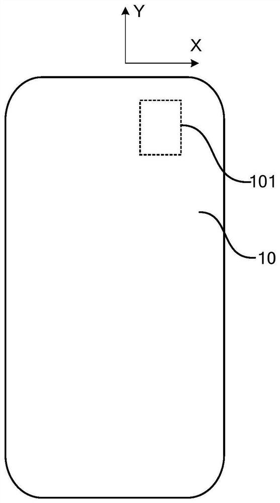
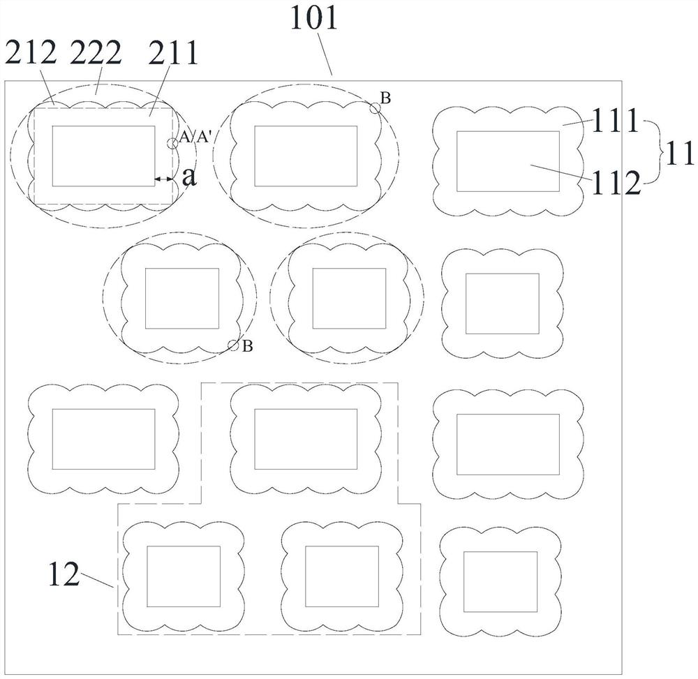
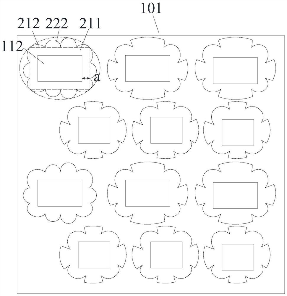
[0023] An embodiment of the present invention provides a display panel. figure 1 It is a schematic structural diagram of a display panel provided by an embodiment of the present invention. figure 2 An enlarged schematic diagram of a partial structure of a light-transmitting display area of ​​a display panel provided by an embodiment of the present invention. combine figure 1 and figure 2 As shown, the display panel 10 has a light-transmitting display area 101 . A plurality of sub-pixels 11 are arranged in th...


PUM


Abstract

The invention provides a display panel. The display panel comprises a light-transmitting display region, and is characterized in that: a plurality of sub-pixels are arranged in the light-transmittingdisplay region; the sub-pixels are linearly arranged at intervals in at least one direction; and each sub-pixel comprises a light-emitting region and a lower electrode, the light-emitting region is ina square shape, the lower electrode is arranged on the side, away from the light-emitting surface, of the light-emitting region, the shape of the outer edge of the lower electrode is irregular, and the projection of the light-emitting region on the lower electrode is located in the lower electrode in the thickness direction of the display panel. Therefore, the problem of diffraction of the display panel is solved, the area of the light-transmitting region is increased, and the light transmittance is improved.

Description

technical field [0001] Embodiments of the present invention relate to the field of display technology, and in particular, to a display panel and a display device. Background technique [0002] With the rapid development of electronic devices, users have higher and higher requirements for screen-to-body ratio. In order to achieve a true full screen, the display panel in the camera area is still equipped with pixels, and the light reaches the camera through the slits between the pixels to realize the shooting function. However, in the conventional design, external light will be diffracted when passing through the slit area of ​​the display panel, which seriously affects the shooting effect of the camera. Contents of the invention [0003] Embodiments of the present invention provide a display panel and a display device to solve the diffraction problem of the display panel, increase the area of ​​the light-transmitting region, and increase the light transmittance. [0004] I...

Claims


Application Information

Patent Timeline
Patent Type & Authority Applications(China)
IPC IPC(8): H01L51/52H01L27/32H04N5/225
CPCH04N23/57H10K59/353H10K59/65H10K59/12H10K50/813
Inventor 许传志谢正芳张露胡思明
Owner KUNSHAN GO VISIONOX OPTO ELECTRONICS CO LTD
Why Eureka
Try Eureka