Isolated fireproof power distribution cabinet

A power distribution cabinet and cabinet technology, which is applied in the substation/distribution device shell, electrical components, fire rescue and other directions, can solve the problems of paralysis of the whole set of equipment, direct economic losses, and no automatic fire extinguishing device in the power distribution cabinet.

Inactive Publication Date: 2020-10-23
成春萍
View PDF4 Cites 6 Cited by
  • Summary
  • Abstract
  • Description
  • Claims
  • Application Information

AI Technical Summary

Problems solved by technology

[0004] The purpose of the present invention is to solve the disadvantages existing in the prior art that the existing power distribution cabinets do not have suitable automatic fire extinguishing devices, and cannot control the fire in time, which easily leads to the paralysis of the whole set of equipment, and then causes huge direct economic losses. Proposed a kind of isolated fireproof power distribution cabinet

Method used


Image

  • Isolated fireproof power distribution cabinet
  • Isolated fireproof power distribution cabinet
  • Isolated fireproof power distribution cabinet

Examples


Embodiment 1

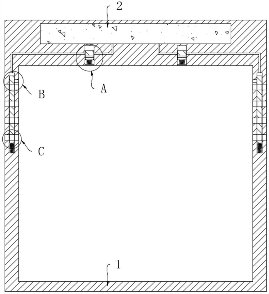
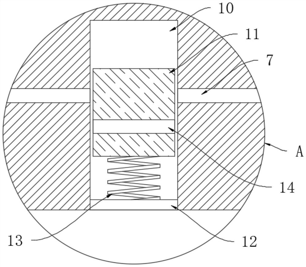
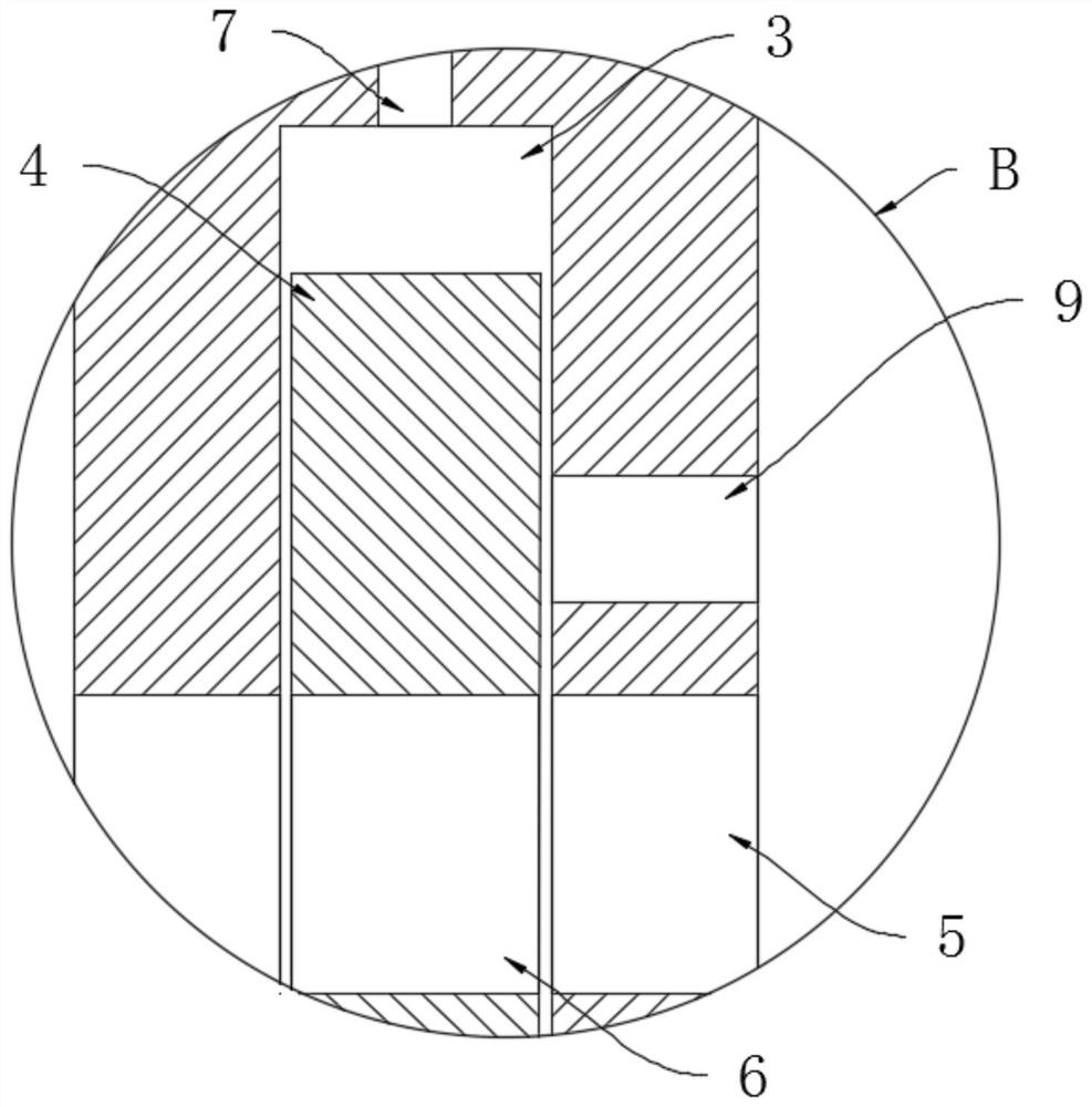
[0021] refer to Figure 1-4 , an isolated fireproof power distribution cabinet, including a cabinet body 1 for installing electrical devices, a liquid storage tank 2 for filling a fire extinguishing agent is opened at the upper end of the cabinet body 1, and the fire extinguishing agent is high-pressure carbon dioxide gas, and the side wall of the cabinet body 1 The upper end is symmetrically provided with chute 3, and each chute 3 is elastically connected with a slider 4 through a return spring 8, and each slider 4 is sealed and slidably connected with the corresponding chute 3, and the groove wall of each chute 3 There are vents 5 that connect the chute 3 with the outside world and the interior of the cabinet body 1 symmetrically on the top. Each slider 4 is provided with a plurality of through holes 6 that cooperate with the vents 5. The grooves of each chute 3 The upper end of the wall is provided with an air intake pipe 9 connecting the chute 3 with the interior of the ca...

Embodiment 2

[0027] refer to Figure 5-6 The difference between this embodiment and Embodiment 1 is that: the lower end of the side wall of the cabinet body 1 is symmetrically provided with a second control groove 15, and the inner bottom wall of each second control groove 15 is elastically connected with a piston through a second memory spring 16. plate 17, and the side walls of each piston plate 17 are sealed and slidably connected with the groove wall of the corresponding second control groove 15, and the second memory spring 16 can be made of a thermally deformable metal material with a transformation temperature of about 200 degrees Celsius. A connecting pipe 18 is connected between the top groove wall of the second control groove 15 and the corresponding drive zone, and the sealed space formed by the upper end surface of the piston plate 17 and the second control groove 15 is a control zone, and each control zone is connected to the corresponding drive zone. The connecting pipes 18 a...


PUM


Abstract

The invention discloses an isolated fireproof power distribution cabinet which comprises a cabinet body, the upper end of the cabinet body is provided with a liquid storage tank used for being filledwith a fire extinguishing agent, the upper end of the side wall of the cabinet body is symmetrically provided with sliding grooves, each sliding groove is internally and elastically connected with a sliding block through a reset spring, and each sliding block is connected with the corresponding sliding groove in a sealed and sliding mode. When a fire breaks out in the cabinet body, high-pressure carbon dioxide gas in a liquid storage tank can be quickly released and sprayed into the cabinet body by utilizing a first memory spring so as to control the fire behavior, meanwhile, a plurality of ventilation openings can be blocked; high-pressure carbon dioxide gas is prevented from escaping to the outside through the ventilation opening, carbon dioxide gas filled in the cabinet body can be stored in the cabinet body for a longer time, flames can be conveniently and thoroughly extinguished, a plurality of positions in the cabinet body can be monitored and processed in time by arranging a plurality of second control grooves and second memory springs, the fire extinguishing reaction speed of the device is increased, and the use effect is good.

Description

technical field [0001] The invention relates to the technical field of electric equipment, in particular to an isolated fireproof power distribution cabinet. Background technique [0002] Many power devices need to be installed in the corresponding power distribution cabinets to avoid damage to the power devices. However, when the power devices run for a long time, they generate a lot of heat, especially during peak power consumption periods. If the heat cannot be discharged in time, it will have a great impact on the normal operation of the power device, and sometimes even cause the power device to break and catch fire. There are many power devices in the power distribution cabinet. Timely control of the fire can easily lead to the paralysis of the entire set of equipment, resulting in huge direct economic losses. [0003] However, many power distribution cabinets are installed outdoors or away from people. When these power distribution cabinets catch fire, it is difficult...

Claims


Application Information

Patent Timeline
Patent Type & Authority Applications(China)
IPC IPC(8): H02B1/28H02B1/56H02B1/30H02B1/32A62C37/11
CPCA62C37/11H02B1/28H02B1/30H02B1/306H02B1/32H02B1/565
Inventor 成春萍
Owner 成春萍
Why Eureka
Try Eureka