Novel girder-free photovoltaic module mounting bracket

A technology for photovoltaic modules and mounting brackets, which is applied to the support structure of photovoltaic modules, photovoltaic modules, photovoltaic power generation, etc., can solve the problems of complex structure, multiple labor, and complexity.

Pending Publication Date: 2020-10-23
JIANGSU LINYANG ENERGY CO LTD +3
View PDF0 Cites 1 Cited by
  • Summary
  • Abstract
  • Description
  • Claims
  • Application Information

AI Technical Summary

Problems solved by technology

Traditional fixing brackets have been widely used, of which beams and purlins account for about 70%, the overall structure is relatively complex, and more labor is required for production, processing, manufacturing and installation
[0003] The structure of the existing ground power station is complex, with dozens of main components, and each piece needs to be manufactured separately, which is relatively very complicated and inconvenient for transportation and installation

Method used


Image

  • Novel girder-free photovoltaic module mounting bracket
  • Novel girder-free photovoltaic module mounting bracket
  • Novel girder-free photovoltaic module mounting bracket

Examples


Embodiment 1

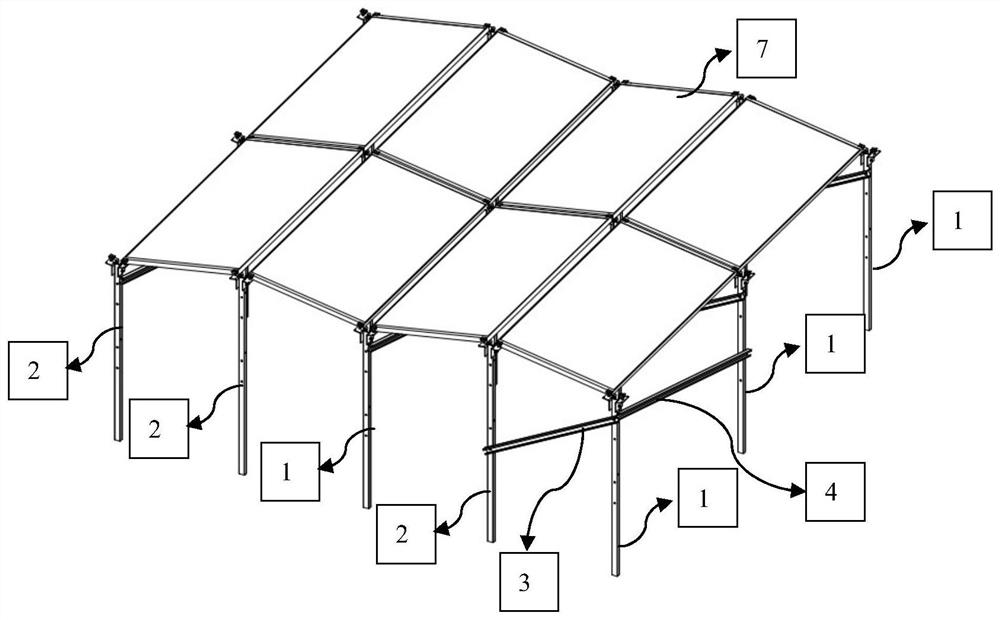
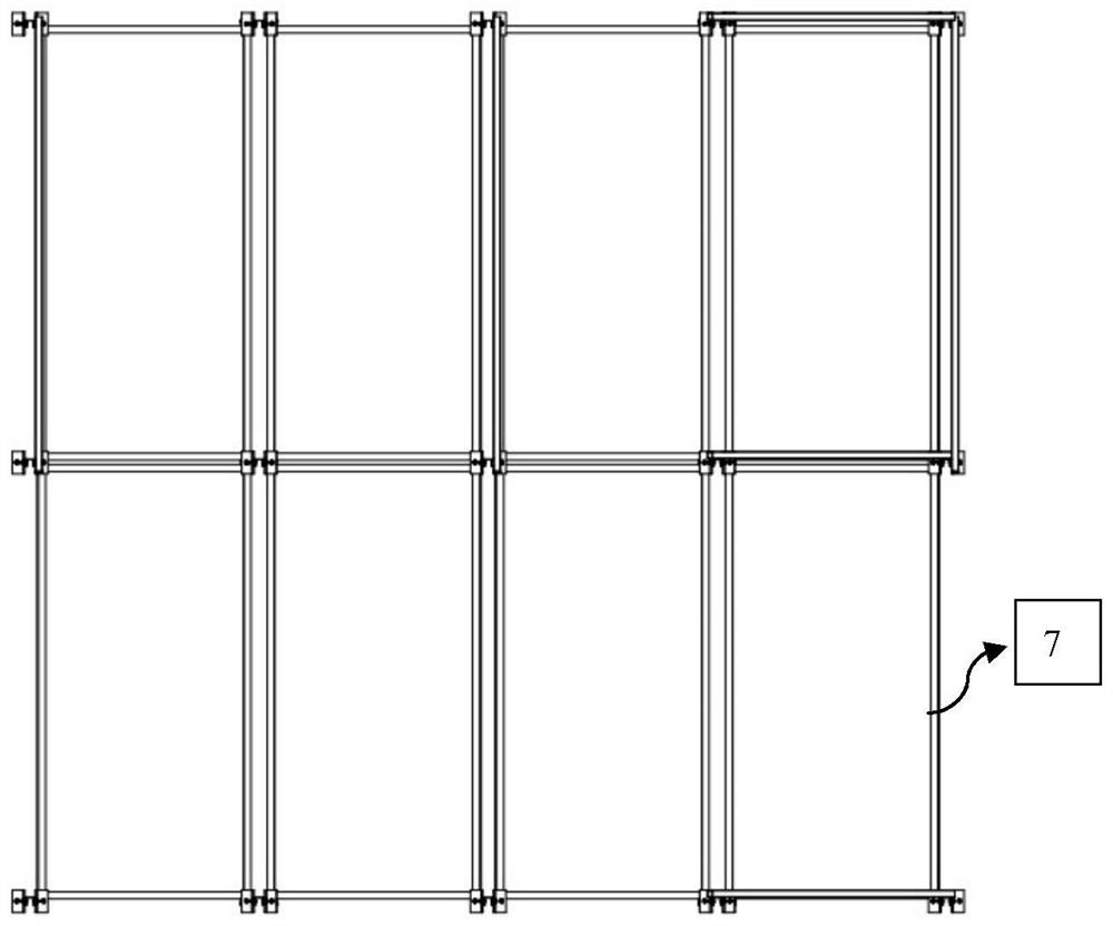
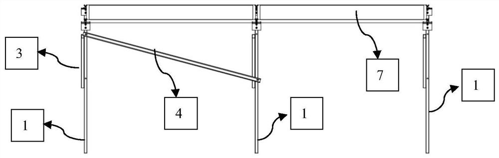
[0038] The present invention is a new main-beam-less photovoltaic module mounting bracket. The photovoltaic bracket provided by this scheme has a simple structure, a small number of parts, and a simple production process; the main parts of this structure are only three kinds-upright columns, diagonal braces and nodes The plate, column and diagonal brace are of the same cross-section, and the overall processing is simple; specific, such as figure 1 As shown, the photovoltaic support includes:

[0039] A column, the column is installed vertically, and is used to provide the supporting force in the vertical direction for the photovoltaic module;

[0040] Diagonal bracing, the diagonal bracing is installed at an angle to the horizontal direction, and its two ends are fixed on the column;

[0041] A gusset plate, the gusset plate is installed on the column, mounting holes are provided on different heights of the column for installing the gusset plate, through the mounting hole, th...

Embodiment 2

[0056] Based on a new main-beam-free photovoltaic module mounting bracket provided in Example 1, this embodiment provides an assembly method for the photovoltaic bracket. After the first column and the second column are driven into the ground by a piling machine, diagonal braces are installed to control the overall After stabilization, install the first and second gusset plates (No. 5 and 6) and adjust to the angle and height required by the design, then install the components, and fix the components on the adjustment plate with pressing blocks.

[0057] The assembly process of the bracket is convenient, which solves the problem of a large number of bracket parts and inconvenient installation. The number of parts is small, and each is relatively independent, and the production, transportation and installation are easy to operate, which can greatly improve the photovoltaic bracket system. production efficiency and installation efficiency. The components used in the invention ca...


PUM


Abstract

The invention discloses a novel girder-free photovoltaic module mounting bracket, which comprises stand columns, inclined struts and gusset plates, wherein the stand columns are vertically mounted andare used for providing supporting forces in the vertical direction for photovoltaic modules; the inclined struts are installed at an angle with the horizontal direction, and the two ends of the inclined struts are fixed to the stand columns; the gusset plates are installed on the stand columns, and installation holes are formed in the stand columns at different heights and used for installing thegusset plates; each gusset plate comprises at least two intersected planes, one plane is a fixed plane, and the other plane is an adjusting plane; the photovoltaic assemblies are placed on the fixedplanes; and the photovoltaic assemblies are fixed by means of fixing pieces. The novel girder-free photovoltaic module mounting bracket only has three kinds of main components, namely the stand columns, the inclined struts and the gusset plates, is simple and convenient to produce, manufacture, transport and install, and can improve the production efficiency and the installation efficiency of a photovoltaic bracket system to a great extent.

Description

technical field [0001] The patent of the invention belongs to the technical field of photovoltaic modules, specifically the installation structure scheme of single-sided / double-sided framed solar photovoltaic modules applied to the installation scenarios of ground and flat roofs. Background technique [0002] The existing ground and roof photovoltaic supports are basically beams and purlins as the main load-bearing structure, and a corresponding number of columns are auxiliary configured to support the beams and purlins, and corresponding structures such as braces, braces, and purlins are equipped to meet the corresponding structural requirements. , this kind of fixing bracket we call traditional fixing bracket. Traditional fixing brackets have been widely used, of which beams and purlins account for about 70%, the overall structure is relatively complex, and more labor is required for production, processing, manufacturing and installation. [0003] The structure of the exi...

Claims


Application Information

Patent Timeline
Patent Type & Authority Applications(China)
IPC IPC(8): H02S20/30H02S20/23H02S20/10F24S25/61F24S25/70
CPCF24S25/61F24S25/70H02S20/10H02S20/23H02S20/30Y02B10/10Y02B10/20Y02E10/47Y02E10/50
Inventor 陈桂佳王亚晶张勇成潘少峰索博鹏田介花裴骏陆永华
Owner JIANGSU LINYANG ENERGY CO LTD
Why Eureka
Try Eureka