
Condensing device of cooking equipment and cooking equipment

A condensing device and cooking equipment technology, which is applied to the structure of cooking utensils, steam cooking utensils, lighting and heating equipment, etc., which can solve the problems of large space occupation and poor condensation effect

Active Publication Date: 2020-10-27
GUANGDONG MIDEA KITCHEN APPLIANCES MFG CO LTD +1
View PDF13 Cites 0 Cited by
  • Summary
  • Abstract
  • Description
  • Claims
  • Application Information

AI Technical Summary

Problems solved by technology

For this reason, the present invention proposes a condensing device for cooking equipment. The condensing device integrates steam distribution and condensation, has small volume, fast steam condensation, and good condensed water collection effect. The problem of poor effect and large space occupation

Method used


Image

  • Condensing device of cooking equipment and cooking equipment
  • Condensing device of cooking equipment and cooking equipment
  • Condensing device of cooking equipment and cooking equipment

Examples


Embodiment 1

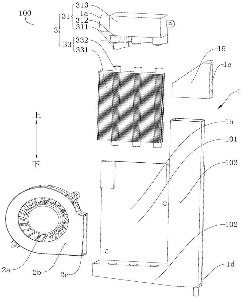
[0095] A condensing device 100, such as figure 1 As shown, it includes: a steam distribution shell 1, a fan 2a and a steam condensing assembly 3.

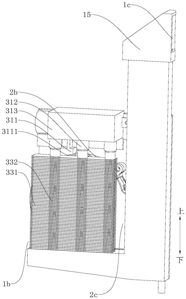
[0096] Among them, such as figure 1 and Figure 6 As shown, an air passage chamber 101 , an exhaust chamber 103 and a drainage chamber 102 are formed in the steam distribution housing 1 . Such as figure 1 As shown, the steam distribution shell 1 is provided with a second air inlet 1b, an air exhaust port 1e and a mixed air exhaust port 1c, the exhaust chamber 103 is provided with a mixed air exhaust port 1c, the exhaust chamber 103 and the The air chambers 101 communicate with each other through the air outlet 1e. . Such as figure 1 and figure 2 As shown, the steam condensing assembly 3 is detachably connected in the air passage chamber 101, the first air inlet 1a is formed on the steam condensing assembly 3 to let in high-temperature steam, the outlet of the steam condensing assembly 3 communicates with the drain chamber 1...

Embodiment 2

[0099] A condensing device 100, such as figure 1 As shown, it includes: a steam distribution shell 1, a fan 2a and a steam condensing assembly 3.

[0100] Different from Example 1, as Figure 5 and Figure 6 As shown, the steam distribution housing 1 includes: a first mounting plate 11 , a plurality of second mounting plates 12 and a plurality of third mounting plates 13 . Among them, such as Figure 6 As shown, a plurality of second mounting plates 12 are connected to the bottom of the first mounting plate 11 , and the plurality of second mounting plates 12 enclose to form a drainage chamber 102 . Such as Figure 6 As shown, a plurality of third mounting plates 13 are connected between the first mounting plate 11 and the second mounting plate 12, and the plurality of third mounting plates 13 surround and form an exhaust chamber 103, and the exhaust chamber 103 communicates with the drainage chamber 102 With the wind chamber 101 and the exhaust chamber 103, an air outlet ...

Embodiment 3

[0103] A condensing device 100, such as figure 1As shown, it includes: a steam distribution shell 1, a fan 2a and a steam condensing assembly 3.

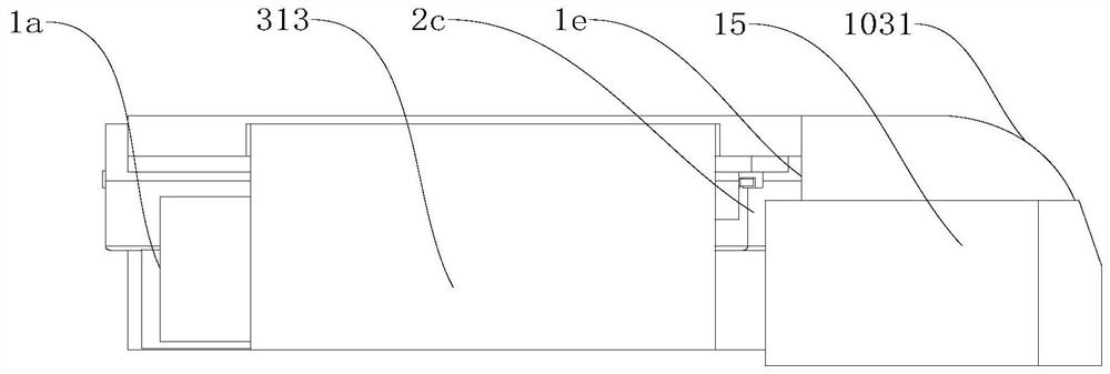
[0104] The difference from Example 2 is that, as Figure 6 and Figure 7 As shown, the wall surface of the exhaust chamber 103 facing the air outlet 1e forms an arc surface 1031 . Such as figure 1 As shown, the top of the exhaust chamber 103 is detachably connected with an exhaust head 15, such as Figure 4 As shown, one side of the exhaust head 15 forms the mixed air exhaust port 1c, and the top of the exhaust head 15 is inclined downward toward the direction away from the mixed air exhaust port 1c. Fan 2a is a diagonal flow fan.

[0105] A cooking device 1000, such as Figure 10 As shown, it includes a machine body 200 and a condensing device 100 . The difference from the second embodiment is that the condensing device 100 is the condensing device 100 described in the third embodiment.


PUM


Abstract

The invention discloses a condensing device of cooking equipment and cooking equipment. The condensing device comprises a steam distributing shell, a steam condensing assembly and a fan. An air passing chamber and a water discharging chamber are formed in the steam distributing shell, a second air inlet, an air outlet and a mixed air outlet are formed in the steam distributing shell, the mixed airoutlet is formed in an air exhausting chamber, and the air exhausting chamber is communicated with the air passing chamber through the air outlet. The steam condensing assembly is detachably connected into the air passing chamber, a first air inlet is formed in the steam condensing assembly to introduce high-temperature steam, an outlet of the steam condensing assembly is communicated with the water discharging chamber, and the water discharging chamber is communicated with the air exhausting chamber. The fan is arranged in the air passing chamber, the steam condensing assembly is arranged between the fan and the second air inlet, and the exhaust end of the fan communicates with the exhaust outlet. The condensing device is small in overall arrangement size, high-temperature steam can be rapidly condensed, the condensation continuity is good, condensate water is easy to collect, the temperature of mixed air formed in the air exhaust process is low, and steam striking is avoided.

Description

technical field [0001] The invention belongs to the technical field of living appliances, in particular to a condensing device for cooking equipment and the cooking equipment. Background technique [0002] In related technologies, steamers, ovens or steam ovens generate high-temperature steam during cooking. When it is necessary to take the cooked food, if the door is opened directly, it is easy to form high-temperature steam on the face, causing the problem of facial burns and reducing the user experience. Air curtains have been used to block the steam sprayed upwards when the door is opened to solve the problem of steam hitting the face, but there are still more high-temperature steam sprayed into the room from many places, resulting in humid indoor environment and easy damage to the cabinet. There are also components such as rollers for cooling, which occupy a large volume, are inconvenient to arrange, and the condensed water is not easy to collect; Problem with poor co...

Claims


Application Information

Patent Timeline
IPC IPC(8): A47J27/00A47J27/04A47J36/00A47J36/38A47J37/06F28B1/06
CPCA47J27/002A47J27/04A47J36/00A47J36/38A47J37/0623F28B1/06
Inventor 奚俊男司鹏唐相伟赵鹏飞张红帅霍延凯黄韬妃
Owner GUANGDONG MIDEA KITCHEN APPLIANCES MFG CO LTD
Learn More