Operating manipulator of otorhinolaryngologic endoscope
An ENT and endoscope technology, applied in the field of manipulators, can solve the problems of not being able to improve the comfort of the endoscope
- Summary
- Abstract
- Description
- Claims
- Application Information
AI Technical Summary
Problems solved by technology
Method used
Image
Examples
specific Embodiment approach 1
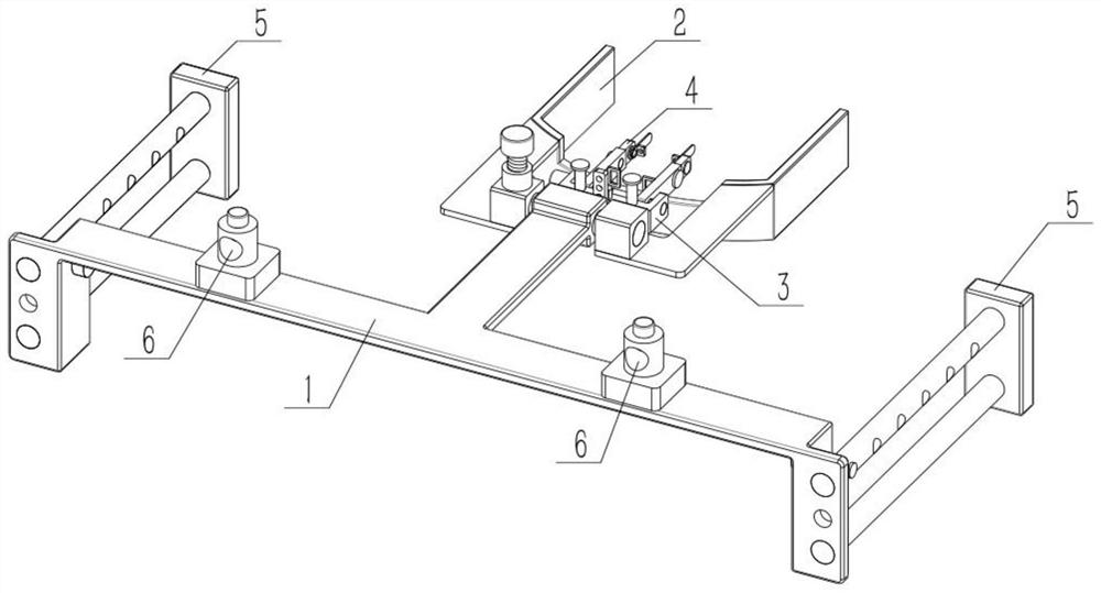
[0031] Such as Figure 1-9 As shown, a manipulator for operating an ENT endoscope includes a dual-purpose arm support 1, a head positioner 2, an adjuster 3, a support guide 4, a dual-purpose support 5 and a support portion 6, and the dual-purpose arm The front end of the support 1 is rotated to connect the head positioner 2, the adjuster 3 is connected to the head positioner 2, two supporters 4 are mirror-symmetrical, and the two supporters 4 are respectively connected to the left and right sides of the adjuster 3, There are two dual-use supports 5 symmetrically, and the two dual-use supports 5 are respectively connected to the left and right sides of the dual-use arm support 1, and the left and right sides of the upper end of the dual-use arm support 1 are rotatably connected to a support part 6.
specific Embodiment approach 2
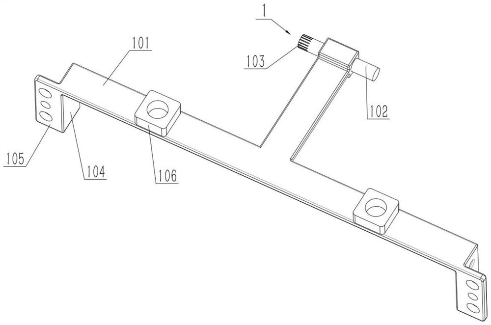
[0033] Such as Figure 1-9 As shown, the dual-purpose arm support 1 includes an arm support body 101, a shaft 102, a plate I 104, and a plate II 105. For the connected plate I104, the outer ends of the rear ends of the two plates I104 are provided with an integrally connected plate II105, and the plate I104 and the plate II105 are perpendicular to each other. The dual-purpose arm support 1 can be used in a vertical position, which is convenient for the user to use in a sitting position, and is convenient for assisting the user in short-term treatment. The dual-purpose arm support 1 can also be used horizontally, which is convenient for the user to use in a flat or lying state, and is convenient for assisting the user in long-term treatment. refer to figure 1 with figure 2 , at this time, the dual-purpose arm support 1 is used in a horizontal manner, and when the rear end surface of the plate II 105 is brought into contact with a horizontal surface and erected, it is used i...
specific Embodiment approach 3
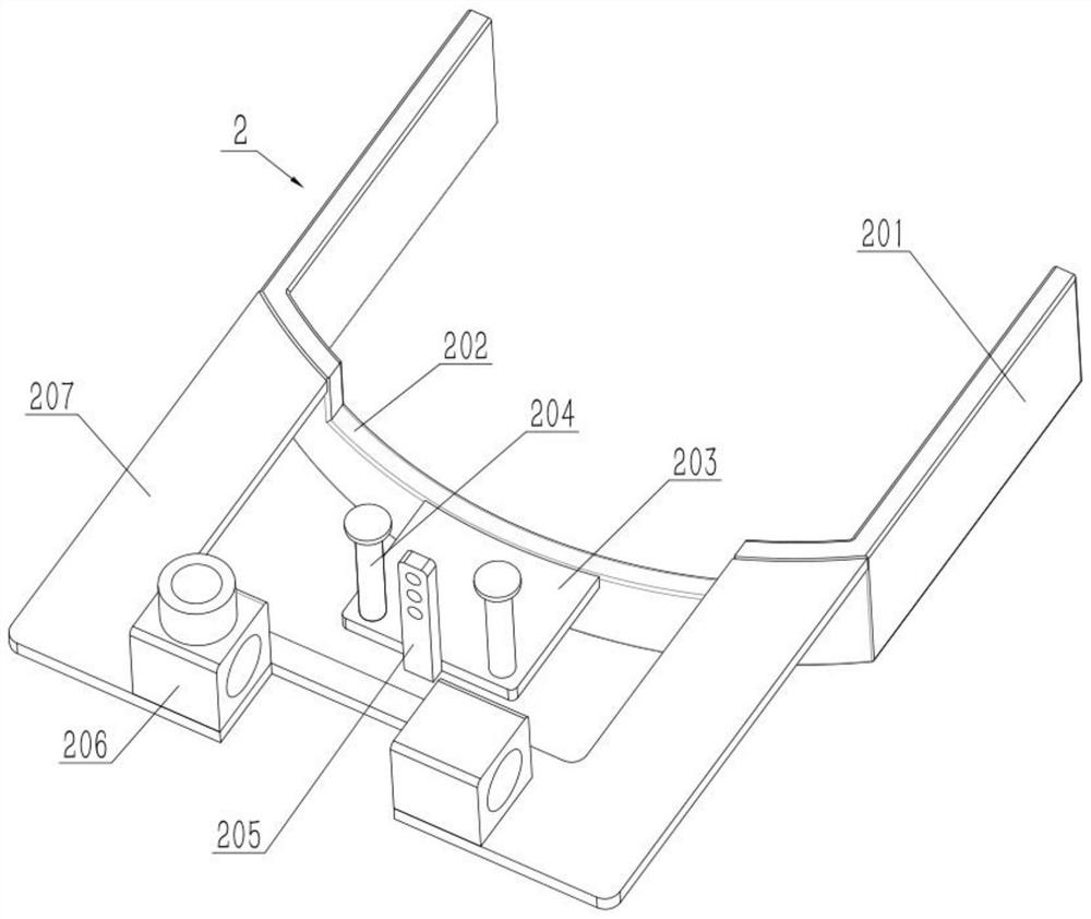
[0035] Such as Figure 1-9 As shown, the head positioner 2 includes a head positioner body 201, a sinking groove 202, a shaft seat 206 and an extension plate 207, the upper end of the head positioner body 201 rear end is provided with a sinking groove 202, and the extension plate 207 is fixed on The rear end of the head positioner body 201, the left and right sides of the upper rear end of the head positioner body 201 are fixedly connected with an axle seat 206; The upper end of the seat 206 is threaded with a screw rod, and the screw rod is screwed into the shaft seat 206 on the left side to contact the shaft 102 from bottom to bottom, and the handle I is fixedly connected to the upper end of the screw rod. When using in a vertical position, the user places the head around the head positioner body 201 , rests the chin on the rear side of the head positioner body 201 , and places the chin at the sinking groove 202 .
PUM
 Abstract
Description
Claims
Application Information
 - R&D
- Intellectual Property
- Life Sciences
- Materials
- Tech Scout
- Unparalleled Data Quality
- Higher Quality Content
- 60% Fewer Hallucinations
Browse by: Latest US Patents, China's latest patents, Technical Efficacy Thesaurus, Application Domain, Technology Topic, Popular Technical Reports.
© 2025 PatSnap. All rights reserved.Legal|Privacy policy|Modern Slavery Act Transparency Statement|Sitemap|About US| Contact US: help@patsnap.com


