Dry powder extinguisher
A fire extinguisher and dry powder technology, applied in fire rescue and other directions, can solve the problems of missing the best fire extinguishing time, wasting fire extinguishing time, and difficult to spray dry powder.
- Summary
- Abstract
- Description
- Claims
- Application Information
AI Technical Summary
Problems solved by technology
Method used
Image
Examples
Embodiment 1
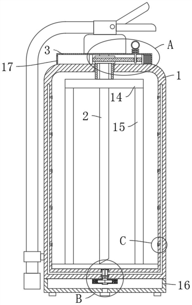
[0028] refer to Figure 1-4 , a dry powder fire extinguisher, comprising a fire extinguisher 1 and a powder suction pipe 2, the upper end of the fire extinguisher 1 is fixedly connected with a rectangular box 3, the inner top of the fire extinguisher 1 is rotatably connected with a hollow sleeve 4, and the powder suction pipe 2 is located inside the hollow sleeve 4 The lower end of the hollow sleeve 4 is fixedly connected with a horizontal plate 14, and the outer edge of the lower end of the horizontal plate 14 is fixedly connected with a plurality of uniformly distributed stirring rods 15, and the inside of the rectangular box 3 is provided with a driving device connected with the hollow sleeve 4, The lower end of the fire extinguisher 1 is fixedly connected with a gas storage tank 16 storing high-pressure gas. An auxiliary air injection device is provided between the gas storage tank 16 and the inner wall of the fire extinguisher 1. When in use, the stirring rod 15 is driven ...
Embodiment 2
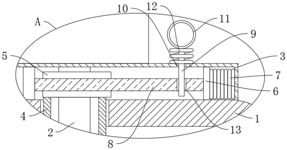
[0031] refer to figure 1 and figure 2 , is basically the same as Embodiment 1, furthermore: the driving device includes a slide plate 6 slidably connected in the rectangular box 3, the slide plate 6 is elastically connected with the right side inner wall of the rectangular box 3 by a return spring 7, and the left side of the slide plate 6 The side wall is fixedly connected with a rack 8, the upper end of the hollow sleeve 4 extends into the rectangular box 3 and is fixedly connected with a gear 5 meshing with the rack 8, the upper end of the rectangular box 3 is provided with a chute 10, and the chute 10 slides Connected with plunger 9, the upper end of plunger 9 is fixedly connected with draw ring 11, and the upper end of rack 8 is provided with the jack 13 that cooperates with plunger 9, by pulling draw ring 11, the lower end of draw ring 11 from jack 13 Slide out, at this time the rack 8 slides to the left under the action of the return spring 7, so the rack 8 drives the ...
Embodiment 3
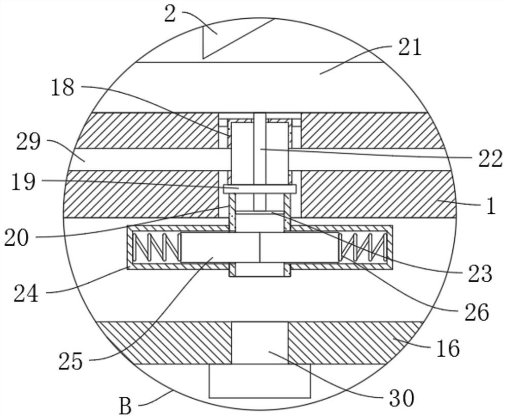
[0036] refer to image 3 and Figure 4, is basically the same as Embodiment 1, furthermore: the auxiliary air injection device includes an end cover 18 fixedly connected to the lower end of the fire extinguisher 1, and the inner wall of the fire extinguisher 1 is fixedly connected with a plurality of evenly distributed vertical pipes 27, and a plurality of vertical pipes 27 The side walls of the fire extinguisher 1 are fixedly installed with nozzles 28 extending into the fire extinguisher 1. A plurality of vertical pipes 27 are fixedly connected and communicated with the end cover 18 through the connecting pipe 29. The lower end of the end cover 18 is rotatably connected with an input pipe 20. The left and right side walls of the left and right side walls are fixedly connected with the device pipe 24 communicating with it, and the two device pipes 24 are slidingly connected with two symmetrically arranged and offset slide bars 25, and the two slide bars 25 are connected to the...
PUM
 Abstract
Description
Claims
Application Information
 - R&D
- Intellectual Property
- Life Sciences
- Materials
- Tech Scout
- Unparalleled Data Quality
- Higher Quality Content
- 60% Fewer Hallucinations
Browse by: Latest US Patents, China's latest patents, Technical Efficacy Thesaurus, Application Domain, Technology Topic, Popular Technical Reports.
© 2025 PatSnap. All rights reserved.Legal|Privacy policy|Modern Slavery Act Transparency Statement|Sitemap|About US| Contact US: help@patsnap.com


