
Shaft sleeve feeding and assembling device for sensor production and shaft sleeve assembling method for sensor production

A technology for assembling devices and sensors, which is applied in the direction of surface coating liquid devices, material gluing, connecting components, etc., and can solve problems such as poor assembly quality of shaft sleeves

Inactive Publication Date: 2020-10-27
林勤鑫
View PDF0 Cites 4 Cited by
  • Summary
  • Abstract
  • Description
  • Claims
  • Application Information

AI Technical Summary

Problems solved by technology

[0005] The purpose of the present invention is to solve the problem of poor assembly quality of the shaft sleeves of the existing sensors mentioned above, and provide a shaft sleeve feeding assembly device for sensor production, which facilitates better connection of the shaft sleeves through the shaft sleeve joint assembly , to improve the rotation efficiency of the shaft sleeve, it is convenient to further limit the shaft sleeve through the circular groove to prevent deviation during the rotation; to further improve the smoothness of rotation through the retaining ring and the retaining ring bearing; to facilitate further Improve the quality of gluing; push the assembly through the sleeve to facilitate further pushing out the sleeve; transfer the assembly components through the sleeve to further improve the assembly quality

Method used


Image

  • Shaft sleeve feeding and assembling device for sensor production and shaft sleeve assembling method for sensor production
  • Shaft sleeve feeding and assembling device for sensor production and shaft sleeve assembling method for sensor production
  • Shaft sleeve feeding and assembling device for sensor production and shaft sleeve assembling method for sensor production

Examples


Embodiment Construction

[0033] The specific implementation manner of the present invention will be described in detail below in conjunction with the accompanying drawings.

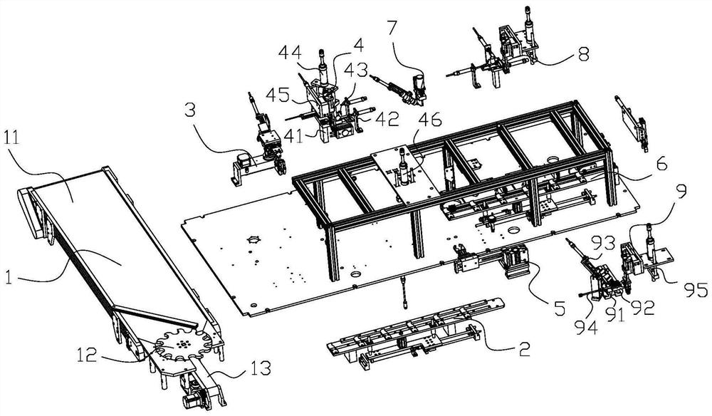
[0034] Such as figure 1 As shown, a sensor automatic production equipment, the equipment includes a frame and a sensor shell feeding device 1 on it, a first horizontal conveying transfer device 2, a shell glue coating device 3, a bearing and a rotating shaft feeding assembly device 4, an overturning Device 5, the second horizontal conveying transfer device 6, the back surface glue coating device 7, the bearing feed assembly device 8, the shaft sleeve feed assembly device 9 and the discharge device; the sensor shell feed device 1, the shell glue coating device 3, Bearing and rotating shaft feeding assembly device 4, turning device 5, housing reverse glue coating device 7, bearing feeding assembly device 8, shaft sleeve feeding assembly device 9 and discharging device are arranged in sequence along the direction of feeding to disch...


PUM


Abstract

The invention belongs to the technical field of automatic sensor production, and discloses a shaft sleeve feeding and assembling device for sensor production. The shaft sleeve feeding and assembling device for the sensor production comprises a shaft sleeve feeding vibrator, a shaft sleeve connecting assembly, a shaft sleeve gluing assembly, a shaft sleeve pushing assembly and a shaft sleeve transferring and assembling assembly; the shaft sleeve feeding vibrator is arranged on a rack in the front-back direction, the shaft sleeve connecting assembly is connected with the discharging end of the shaft sleeve feeding vibrator and used for supporting a shaft sleeve and driving the shaft sleeve to rotate, the shaft sleeve gluing assembly is arranged on one side of the shaft sleeve feeding vibrator and used for gluing the inner ring of the shaft sleeve, the shaft sleeve pushing assembly is used for pushing out the glued shaft sleeve, and the shaft sleeve transferring and assembling assembly isused for transferring and assembling the shaft sleeve. The shaft sleeve feeding and assembling device and the shaft sleeve assembling method have the advantages that the assembling efficiency and theassembling quality of the shaft sleeve and a rotating shaft are improved, and the overall assembling quality of a sensor is improved.

Description

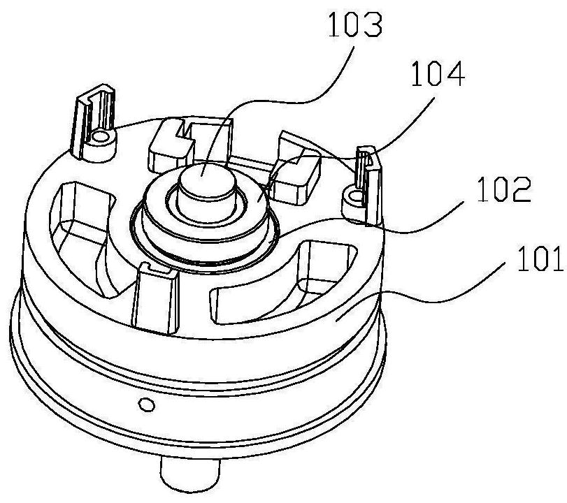
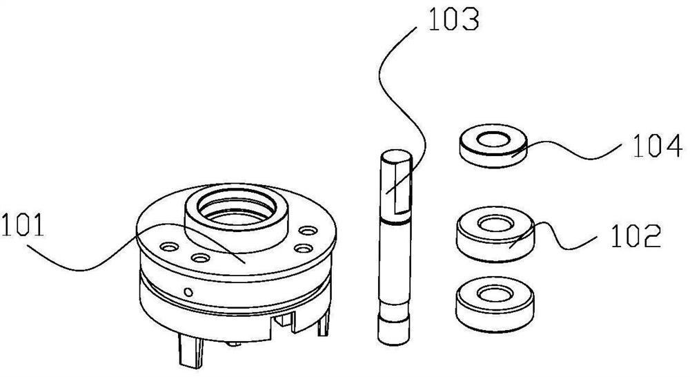
technical field [0001] The invention belongs to the technical field of automatic sensor production, and in particular relates to a shaft sleeve feed assembly device and method for sensor production. Background technique [0002] A sensor is a device that compiles and converts signals or data into signal forms that can be used for communication, transmission and storage. The sensor includes a sensor housing, two bearings located in the upper and lower ends of the sensor housing, a rotating shaft passing through the two bearings and a shaft sleeve sleeved on the rotating shaft. During the production process, the sensor housing is first conveyed into the , apply glue to the front inner ring of the sensor housing, feed the front bearing at the same time, and assemble the front bearing to the sensor housing, then feed the rotating shaft and insert the rotating shaft on the bearing, after the front assembly is completed, put the The sensor housing is rotated 180° to turn over. Af...

Claims


Application Information

Patent Timeline
IPC IPC(8): B05C5/02B05C13/02F16B11/00
CPCB05C5/0208B05C13/02F16B11/006
Inventor 林勤鑫张双河张喜荣
Owner 林勤鑫
Learn More