
Auxiliary lifting supporting leg for steel pipe transport vehicle based on constructional engineering instruments

A technology of construction engineering and auxiliary lifting, which is applied in the directions of transportation and packaging, lifting and manipulating vehicle accessories, vehicle maintenance, etc. It can solve the problems of inconvenient lifting of steel pipes, manual handling, and prone to dangerous accidents, etc.

Inactive Publication Date: 2020-10-27
李梁稳
View PDF0 Cites 2 Cited by
  • Summary
  • Abstract
  • Description
  • Claims
  • Application Information

AI Technical Summary

Problems solved by technology

[0004] The purpose of the present invention is to provide an auxiliary lifting leg for a steel pipe transport vehicle based on construction equipment, so as to solve the problem that the existing steel pipes are loaded before transportation due to the influence of the length and shape of the steel pipes proposed in the background art. The steel pipe is not easy to lift directly, and manual handling is required during the lifting and loading process, which greatly increases the labor burden of the staff, and dangerous accidents are prone to occur during the handling and loading process

Method used


Image

  • Auxiliary lifting supporting leg for steel pipe transport vehicle based on constructional engineering instruments
  • Auxiliary lifting supporting leg for steel pipe transport vehicle based on constructional engineering instruments
  • Auxiliary lifting supporting leg for steel pipe transport vehicle based on constructional engineering instruments

Examples


Embodiment Construction

[0027] The following will clearly and completely describe the technical solutions in the embodiments of the present invention with reference to the accompanying drawings in the embodiments of the present invention. Obviously, the described embodiments are only some, not all, embodiments of the present invention. Based on the embodiments of the present invention, all other embodiments obtained by persons of ordinary skill in the art without making creative efforts belong to the protection scope of the present invention.

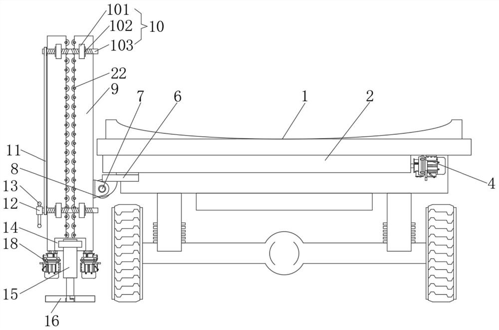
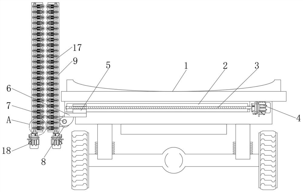
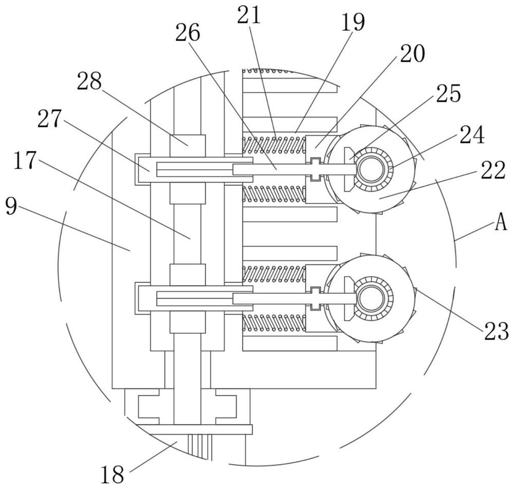
[0028] see Figure 1-7 , an embodiment provided by the present invention: an auxiliary lifting leg for a steel pipe transport vehicle based on construction equipment, including a car body 1, a first servo motor 4, a second servo motor 8, a pulley transmission mechanism 11, a hydraulic telescopic The rod 15 and the third servo motor 18, the slide rail 2 is fixedly installed on the bottom of the compartment body 1, and the inside of the slide rail 2 is inserted ...


PUM


Abstract

The invention relates to the technical field of auxiliary equipment for constructional engineering steel pipe instrument transportation, and particularly relates to an auxiliary lifting supporting legfor a steel pipe transport vehicle based on constructional engineering instruments. The auxiliary lifting supporting leg comprises a carriage main body, a first servo motor, a second servo motor, a belt pulley transmission mechanism, a hydraulic telescopic rod and a third servo motor, a sliding rail is fixedly installed at the bottom of the carriage body, a first screw rod is inserted into the sliding rail in a penetrating mode, one end of the first screw rod is fixedly connected with the first servo motor, and the outer side of the first screw rod is sleeved with a sliding block. Rotating wheels are symmetrically arranged in the two sets of lifting outer frames. Through the rotation of the rotating wheels and the elastic support of springs, a steel pipe can be shifted upwards by the rotating wheels and continuously conveyed upwards, so that the steel pipe is convenient to convey, the manual carrying of a worker is not needed, the labor burden of the worker is effectively reduced, andthe working safety in the lifting process is conveniently guaranteed.

Description

technical field [0001] The invention relates to the technical field of auxiliary equipment for transporting steel pipe equipment for construction engineering, in particular to an auxiliary lifting leg for a steel pipe transport vehicle based on construction engineering equipment. Background technique [0002] With the development and progress of science and technology, people's living standards are improving day by day. With the improvement of people's economic level, the construction of urban agglomerations is becoming more and more perfect. In the construction of existing urban construction projects, it is usually necessary to use steel pipes. The connection and laying of the pipeline realizes water circulation. In the pipeline laying of construction engineering, a large number of steel pipes are used as the main body of the passage connection, so a large number of steel pipes are often required to be transported; [0003] The existing steel pipe transportation device for ...

Claims


Application Information

Patent Timeline
Patent Type & Authority Applications(China)
IPC IPC(8): B60S9/20
CPCB60S9/20
Inventor 李梁稳
Owner 李梁稳
Learn More