Path following model prediction control method, system and device, and storage medium

A model predictive control and following control technology, applied in the field of vehicle cruise control, can solve the problems of reducing the accuracy of vehicle path following control, potential safety hazards, and inability to adapt well

Inactive Publication Date: 2020-10-27
WUHAN UNIV OF TECH
View PDF3 Cites 6 Cited by
  • Summary
  • Abstract
  • Description
  • Claims
  • Application Information

AI Technical Summary

Problems solved by technology

[0004] In the prior art, when designing controller constraint conditions, the tire slip angle constraint value is generally set as a fixed value, but the tire slip angle corresponding to the maximum lateral force is related to factors such as road surface adhesion coefficient and tire vertical load , therefore, this method does not take into account the real-time dynamic change of the tire slip angle, and it cannot be well adapted to the working conditions of different adhesion coefficient road surfaces and the working conditions with large differences in the vertical load of the four wheels, resulting in deviations in the path following control. It reduces the accuracy of the vehicle path following control, and also brings safety hazards to the automatic driving of the vehicle; some studies also restrict the lateral force of the tire, but the value of the maximum lateral force of the tire is related to the road adhesion coefficient. Therefore, this method Poor adaptability to working conditions with unknown road surface adhesion coefficient will also cause the above problems

Method used


Image

  • Path following model prediction control method, system and device, and storage medium
  • Path following model prediction control method, system and device, and storage medium
  • Path following model prediction control method, system and device, and storage medium

Examples


Embodiment Construction

[0057] Embodiments of the present invention are described in detail below, examples of which are shown in the drawings, wherein the same or similar reference numerals designate the same or similar elements or elements having the same or similar functions throughout. The embodiments described below by referring to the figures are exemplary only for explaining the present invention and should not be construed as limiting the present invention. For the step numbers in the following embodiments, it is only set for the convenience of illustration and description, and the order between the steps is not limited in any way. The execution order of each step in the embodiments can be adapted according to the understanding of those skilled in the art sexual adjustment.

[0058] In the description of the present invention, multiple means two or more. If the first and the second are described only for the purpose of distinguishing technical features, it cannot be understood as indicating o...


PUM


Abstract

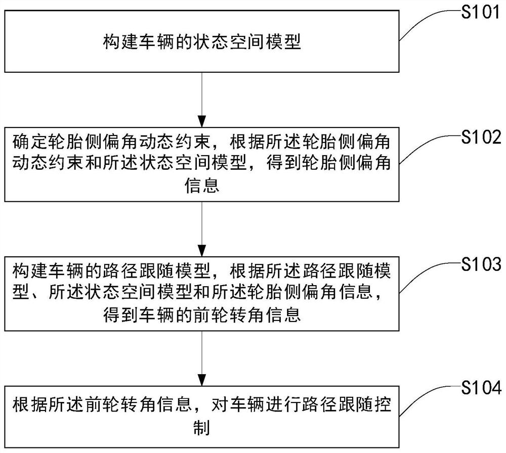
The invention discloses a path following model prediction control method, system and device, and a storage medium. The method comprises the following steps: constructing a state space model of a vehicle; determining a tire slip angle dynamic constraint, and obtaining tire slip angle information according to the tire slip angle dynamic constraint and the state space model; constructing a path following model of the vehicle, and obtaining front wheel rotation angle information of the vehicle according to the path following model, the state space model and the tire slip angle information; and carrying out path following control on the vehicle according to the front wheel rotation angle information. According to the embodiment of the invention, the tire slip angle can be restrained within a reasonable range under different road adhesion coefficients; and a vehicle trajectory tracking capability is brought into full play, trajectory tracking precision is improved while vehicle driving stability is ensured so that the vehicle automatic driving safety and the vehicle path following control accuracy are improved, the overall performance of the vehicle is increased, and the method, the system, the device and the storage medium can be widely applied to the technical field of vehicle cruise control.

Description

technical field [0001] The present invention relates to the technical field of vehicle cruise control, in particular to a path-following model predictive control method, system, device and storage medium. Background technique [0002] Autonomous driving is the key technology to achieve "zero death" in traffic accidents. A self-driving car is essentially a four-wheeled robot that uses sensing technology and computer vision technology to realize the vehicle's perception of the surrounding environment, and then uses the acquired Environmental information such as roads and pedestrians, decision-making and planning of safe driving trajectories, and control of actuators to track the planned trajectories to realize automatic driving functions, thereby improving vehicle driving safety and reliability. Therefore, this key technology has become an important It has been one of the research hotspots in the automotive industry in recent years. New energy vehicles have become the industr...

Claims


Application Information

Patent Timeline
IPC IPC(8): B60W30/14B60W30/18B60W40/00B60W40/10B60W60/00
CPCB60W30/14B60W30/18009B60W40/00B60W40/10B60W60/00
Inventor 付翔孙录哲铁鑫杨凤举刘道远吴森
Owner WUHAN UNIV OF TECH
Why Eureka
Try Eureka