Tire centering device and method

A centering device and tire technology, applied in the direction of transportation and packaging, conveyor objects, conveyors, etc., can solve problems such as falling off, unable to meet the normal input of processing equipment, inconvenient tire fixing, etc.

Inactive Publication Date: 2020-10-27
GUANGZHOU COLLEGE OF SOUTH CHINA UNIV OF TECH
View PDF12 Cites 3 Cited by
  • Summary
  • Abstract
  • Description
  • Claims
  • Application Information

AI Technical Summary

Problems solved by technology

[0004] The purpose of the present invention is to provide a tire centering device and a centering method to solve the problem that when the existing tires are moved and transported on the conveyor belt mentioned in the above background technology, the positi

Method used


Image

  • Tire centering device and method
  • Tire centering device and method
  • Tire centering device and method

Examples


Embodiment 1

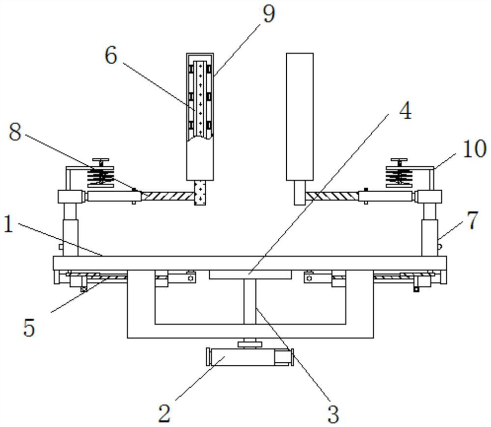
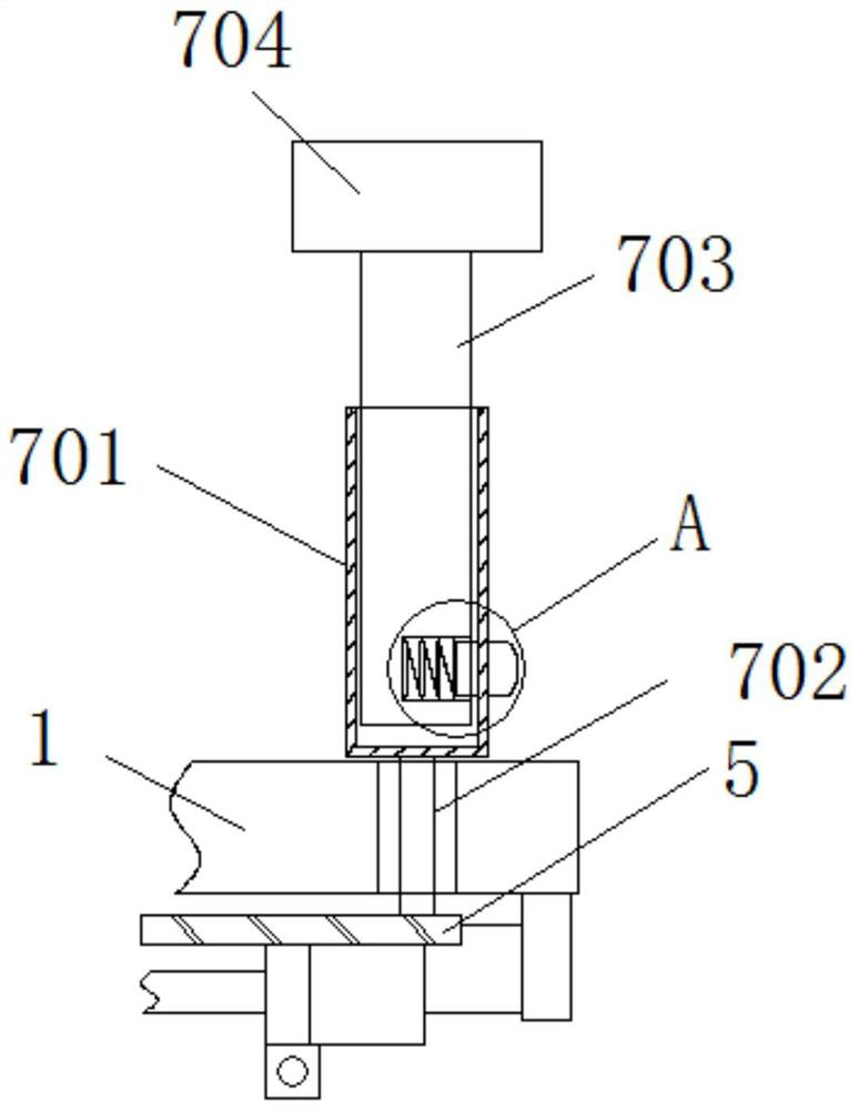
[0049] The present invention provides such Figure 1-7The tire centering device shown includes a mounting frame 1, a cylinder 2 is fixedly installed at the bottom of the mounting frame 1, and a rotating rod 3 is fixedly connected to the top of the cylinder 2, and the rotating rod 3 passes through the bottom end of the mounting frame 1 and is welded to a The center turntable 4, the two sides of the center turntable 4 are fixedly connected with the connecting rod module 5, the upper end of the installation frame 1 is installed with four claws 6, the top of the installation frame 1 is installed with a lifting adjustment mechanism 7, and the inside of the lifting adjustment mechanism 7 includes and installs The telescopic outer rod 701 is movably connected around the top of the frame 1, the bottom end of the telescopic outer rod 701 is welded and connected with a connecting rod 702, the connecting rod 702 is fixedly connected with the connecting rod module 5, and the telescopic out...

Embodiment 2

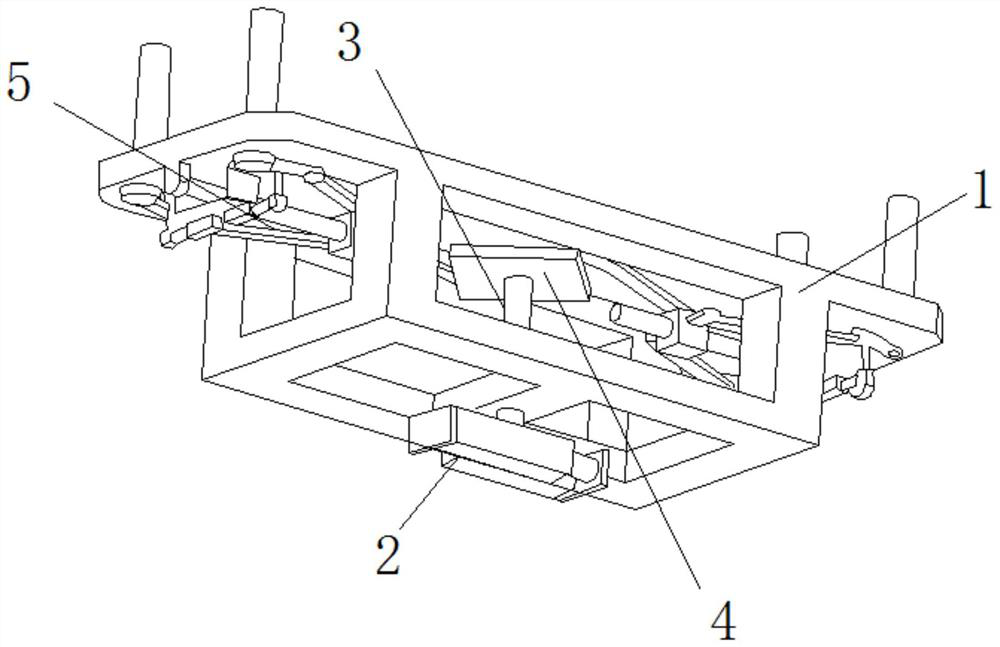
[0052] Specific as Figure 3-4 As shown, the connecting rod 702 is movably socketed with the top of the installation frame 1, and one side of the telescopic outer rod 701 is equidistantly provided with through holes.

[0053] It should be further explained that the telescopic outer rod 701 is fixedly connected to the rotating part of the link module 5 through the connecting rod 702 , and the telescopic outer rod 701 rotates coaxially with the rotating part of the link module 5 .

[0054] Specific as Figure 5 As shown, the interior of the distance adjustment mechanism 8 includes a rotating shaft 801 fixedly connected to one side of the connecting block 704, the other end of the rotating shaft 801 is rotatably connected to a sleeve 802, and the sleeve 802 is internally threaded with a threaded rod 803, and the threaded rod 803 and One side of the claw 6 is welded, and a pin 804 is inserted between the sleeve 802 and the threaded rod 803 .

[0055] It should be further explain...


PUM


Abstract

The invention discloses a tire centering device and method, and relates to the technical field of tire conveying equipment. The tire centering device comprises a mounting frame. An air cylinder is fixedly mounted at the bottom end of the mounting frame, a rotating rod is fixedly connected to the top end of the air cylinder, and the rotating rod penetrates through the bottom end of the mounting frame to be welded to a central rotating disc. Connecting rod modules are fixedly connected to the two sides of the center rotating disc, four clamping jaws are mounted at the upper end of the mounting frame, and a lifting adjusting mechanism is mounted at the top end of the mounting frame. Telescopic outer rods movably connected with the periphery of the top end of the mounting frame are arranged inthe lifting adjusting mechanism, and connecting rods are welded to the bottom ends of the telescopic outer rods. According to the device and the method, the rotating rod of the air cylinder can drivethe center rotating disc to rotate through the air cylinder, the connecting rod modules of the air cylinder drive the four clamping jaws to rotate at the same time, and accordingly, a tire is clampedto the center position. In the working process of a conveying belt, the situation that the tire falls off as the position of the tire is too close to the outer side and normal input of some machiningdevices cannot be met can be prevented.

Description

technical field [0001] The invention relates to the technical field of tire delivery equipment, in particular to a tire centering device and a centering method. Background technique [0002] Tires are ground-rolling circular elastic rubber products assembled on various vehicles or machinery. They are usually installed on metal rims, which can support the body, buffer external impact, realize contact with the road surface and ensure the driving performance of the vehicle. In the conveyor line, the tires on the line need to be centered and positioned. [0003] When the existing tires are moved and transported on the conveyor belt, the position of the tires is often too biased to the outside, resulting in falling off. The tires are fixed. Contents of the invention [0004] The purpose of the present invention is to provide a tire centering device and a centering method to solve the problem that when the existing tires are moved and transported on the conveyor belt mentioned...

Claims


Application Information

Patent Timeline
IPC IPC(8): B65G47/22
CPCB65G47/22B65G2201/0273
Inventor 张建强潘健怡刘楚生徐明昊
Owner GUANGZHOU COLLEGE OF SOUTH CHINA UNIV OF TECH
Why Eureka
Try Eureka