
Dispersed pier anti-collision device

An anti-collision device, a decentralized technology, applied in bridges, bridge parts, bridge construction, etc., can solve the problem of not being able to disperse the impact force of ships

Active Publication Date: 2020-10-27
温州泰乐维工程设计有限公司
View PDF5 Cites 5 Cited by
  • Summary
  • Abstract
  • Description
  • Claims
  • Application Information

AI Technical Summary

Problems solved by technology

[0004] The present invention intends to provide a decentralized pier anti-collision device to solve the problem that the traditional anti-collision structure cannot effectively disperse the impact force of the ship

Method used


Image

  • Dispersed pier anti-collision device
  • Dispersed pier anti-collision device
  • Dispersed pier anti-collision device

Examples


Embodiment

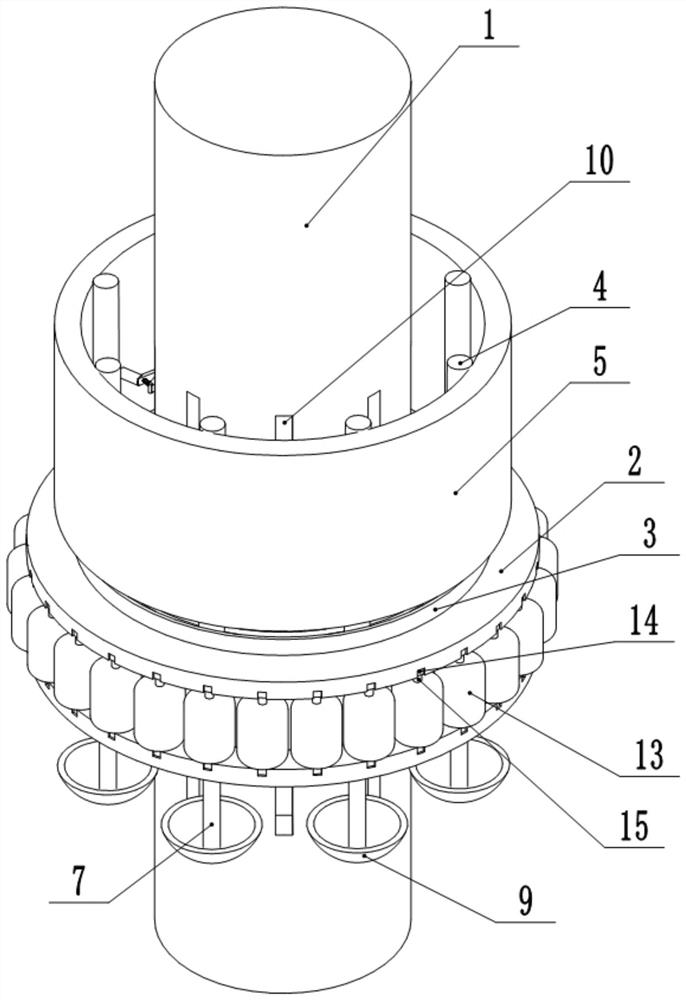
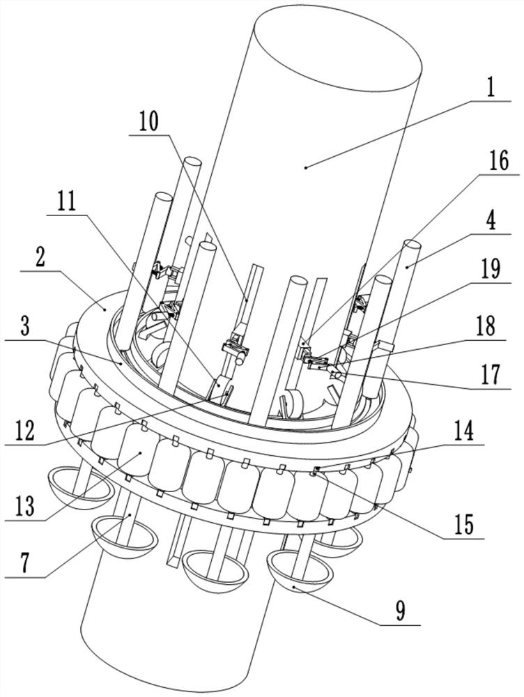
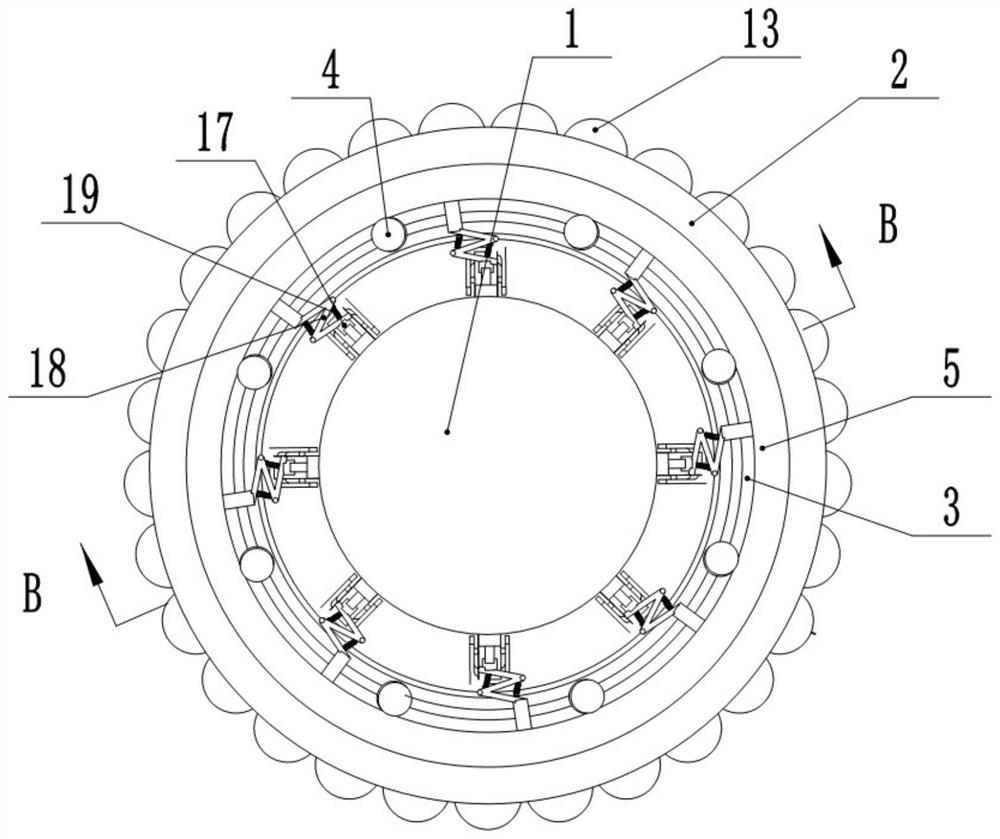
[0024] A decentralized bridge pier anti-collision device, comprising a support platform 2 wrapped on the bridge pier 1, the upper end of the support platform 2 is exposed to the water surface, and an annular slide rail 3 is arranged on the upper surface of the support platform 2, and the slide rail 3 is concentric with the bridge pier 1; A number of connecting columns 4 distributed in a circular array are slidably connected to the slide rail 3, and an annular buffer plate 55 is arranged above the support platform 2. The buffer plate 55 includes an inner layer and an outer layer, the inner layer is a steel plate, and the outer layer is a rubber plate. , rubber particles are filled between the inner layer and the outer layer; the inner layer is fixedly connected to the connecting column 4; the bottom wall of the slide rail 3 is provided with an annular through groove, and the support platform 2 is provided with a number of vertically arranged through holes 6, The through holes 6 ...

specific Embodiment approach

[0025] When the water level changes, the floating rubber cylinder 13 floats up and down with the rise and fall of the water surface, thereby driving the support platform 2 to move up and down; under the cooperation of the support 12, the roller 11 and the groove 10, it is ensured that the support platform 2 moves while, Will not break away from the connection with the pier 1; while the support platform 2 moves, it drives the buffer plate 5 to move, and the buffer plate 5 drives the second slider 16 to slide through the shock absorbing rod 18, ensuring that the gap between the buffer plate 5 and the second slider 16 The damping device can be used normally.

[0026] When the bow of the ship hits the buffer plate 5 at a certain angle with the pier 1, the impact force exerted by the top of the bow makes the buffer plate 5 have a certain rotation tendency, and the buffer plate 5 drives the connecting column 4 on the slide rail 3 while rotating. At the same time, the connecting colu...


PUM


Abstract

The invention relates to the field of bridge construction, and particularly discloses a dispersed pier anti-collision device. The device comprises a supporting table wrapping a pier, the upper end ofthe supporting table is exposed out of the water surface, an annular sliding rail is arranged on the upper surface of the supporting table, and the sliding rail and the pier are concentric; a plurality of connecting columns distributed in a circular array are connected to the sliding rail in a sliding mode, an annular buffer plate is arranged above the supporting table, and the inner wall of the buffer plate is fixedly connected with the connecting columns; an annular through groove is formed in the bottom wall of the sliding rail, a plurality of vertically-formed through holes are formed in the supporting table, the through holes correspond to the connecting columns one to one, and cylinders are vertically connected into the through holes in a sliding mode; a steel cable is fixed to the top end of the cylinder and penetrates through the through groove to be fixed to the bottom end of the connecting column, the bottom end of the cylinder extends downwards out of the supporting table and is immersed in water, and a horizontally and transversely arranged balance weight plate is fixed to the bottom end of the cylinder. The anti-collision structure aims at solving the problem that a traditional anti-collision structure cannot effectively disperse ship impact force.

Description

technical field [0001] The invention relates to the technical field of bridge construction, and specifically discloses a decentralized anti-collision device for bridge piers. Background technique [0002] With the rapid development of the transportation industry, the number of large bridges spanning navigable rivers, port areas and straits recently built in my country has gradually increased, and the number of ships on the waterway has also continued to increase and the ship types tend to be larger, making the bridge and the passage of ships more and more difficult. The contradiction between them is becoming more and more prominent, so the accidents of ships colliding with bridge piers are also increasing. The structural damage caused by the impact of the ship on the bridge reduces the bearing capacity and durability of the bridge within the design life to a certain extent, and even leads to the collapse of the entire structure. [0003] The anti-collision structure of bridg...

Claims


Application Information

Patent Timeline
IPC IPC(8): E02B3/26E01D19/02
CPCE01D19/02E02B3/26Y02A30/30
Inventor 刘玉峰
Owner 温州泰乐维工程设计有限公司
Learn More