
Axial force self-balancing centrifugal chemical pump

A self-balancing, axial force technology, applied in the direction of pumps, pump devices, pump components, etc., can solve problems such as noise pollution, high lateral vibration frequency of chemical pumps, and ground damage

Active Publication Date: 2020-10-27
江苏旭信机械制造有限公司
View PDF6 Cites 0 Cited by
  • Summary
  • Abstract
  • Description
  • Claims
  • Application Information

AI Technical Summary

Problems solved by technology

[0002] Because the liquid chemical raw materials have different densities in different parts, when the liquid chemical raw materials of different densities just enter the water inlet pipe, the lateral driving force on the centrifugal impeller is different, and when the liquid chemical raw materials are extracted, the liquid chemical raw materials at different depths The hydraulic pressure is also different, so that when the chemical pump pumps liquids at different depths, the lateral impact force of the liquid entering the chemical pump on the centrifugal impeller is also different. In addition, when the motor voltage is unstable, the centrifugal impeller speed instability will also cause centrifugation. The head-on thrust of the impeller is different. Due to the intermittent change of the pressure of the pumped liquid, the intermittent change of the density of the pumped liquid, and the change of the voltage, the centrifugal impeller will be subjected to intermittent lateral thrust changes, which will cause the centrifugal impeller to drive the entire device to generate lateral vibration. The superposition of the former makes the lateral vibration frequency of the chemical pump higher, and the vibration will cause ground damage and noise pollution, so people need to provide axial force self-balancing centrifugal chemical pumps to solve the above problems

Method used


Image

  • Axial force self-balancing centrifugal chemical pump
  • Axial force self-balancing centrifugal chemical pump
  • Axial force self-balancing centrifugal chemical pump

Examples


Embodiment

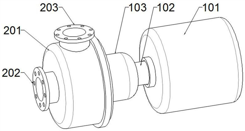
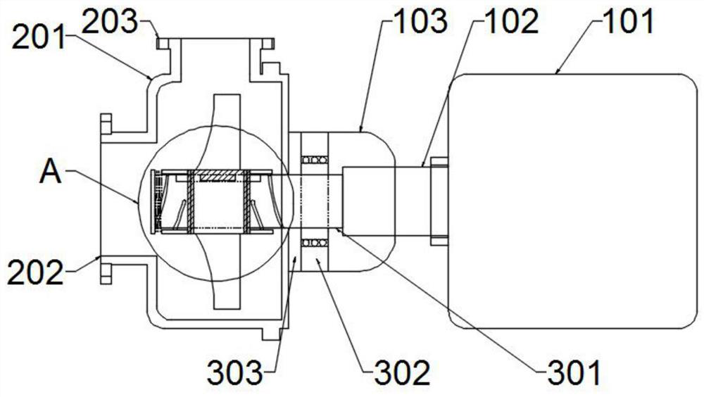
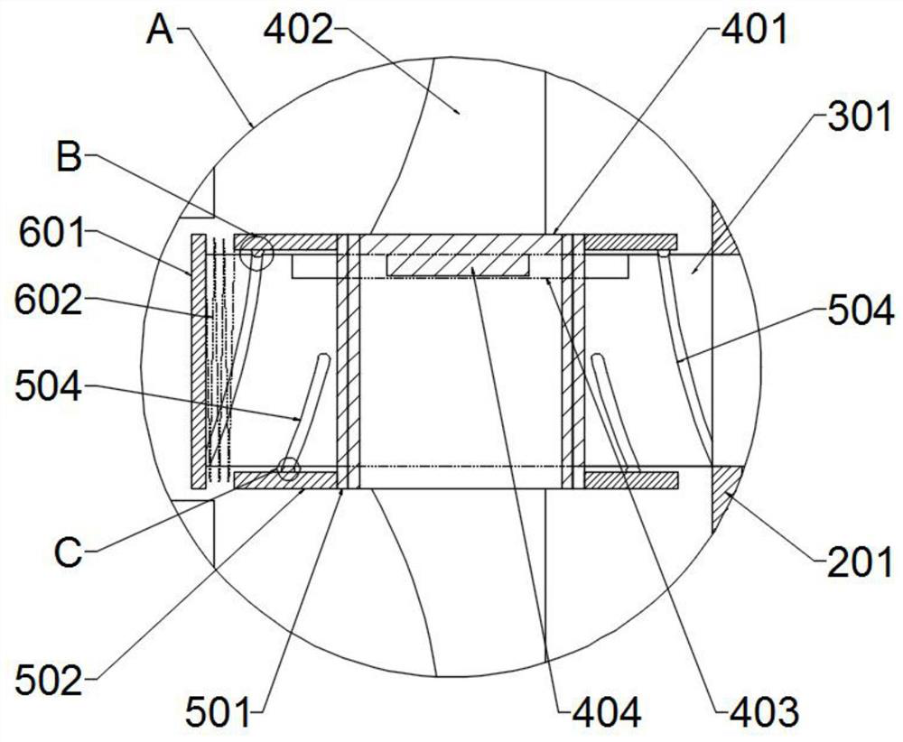
[0025] Example: such as Figure 1~5 As shown, the axial force self-balancing centrifugal chemical pump includes a transmission component, a water channel component, a support shaft component, a lateral movement component, a force relief component, and a reset component. The transmission component is located on one side of the entire device, and the transmission component is of this device Power source, a water channel component is arranged on the side of the transmission component, and the water channel component plays a role of carrying water flow. One end of the transmission component is provided with a supporting shaft component, and the supporting shaft component serves as a stable support for the transmission shaft. It is provided with a lateral movement component which can drive the impeller to move laterally. The lateral movement component is provided with a force relief component which can offset the lateral force received by the impeller inside the pump. A reset compon...


PUM


Abstract

The invention discloses an axial force self-balancing centrifugal chemical pump, and belongs to the technical field of chemical pumps. The pump includes a transmission assembly, a water channel assembly, and a support shaft assembly, the transmission assembly is located on one side of the whole set device, the water channel assembly is arranged on the side part of the transmission assembly, and the support shaft assembly is arranged at one end in the transmission assembly. The pump is scientific and reasonable, and is safe and convenient to use. According to the pump, the horizontal vibrationgenerated by the chemical pump due to intermittent change of the pressure of pumped liquid, the intermittent change of the density of the pumped liquid, and voltage change can be eliminated internally, so that the horizontal vibration force of the chemical pump can be greatly reduced, and the maintenance of the ground and a working environment can be achieved. When the impact force stressed on a centrifugal impeller in a head-on mode of a reset device of the chemical pump is reduced suddenly, a transverse sleeve restores an initial state under the tension action of a reset spring, and under the magnification action of a force unloading hemisphere and a force unloading spiral groove, the reset process is carried out stably, and the vibration is not generated.

Description

Technical field [0001] The invention relates to the technical field of chemical pumps, in particular to axial force self-balancing centrifugal chemical pumps. Background technique [0002] Because the density of each part of the liquid chemical material itself is different, the liquid chemical material of different density has a different lateral driving force on the centrifugal impeller when it enters the water inlet pipe, and when the liquid chemical material is extracted, the liquid chemical material at different depths The hydraulic pressure is also different, so that when the chemical pump pumps liquids at different depths, the liquid entering the chemical pump has different lateral impacts on the centrifugal impeller. In addition, when the motor voltage is unstable, the unstable speed of the centrifugal impeller will also cause centrifugation. The thrust on the impeller is different. Because of the intermittent changes in the pressure of the pumped liquid, the intermittent ...

Claims


Application Information

Patent Timeline
IPC IPC(8): F04D29/041F04D13/06F04D29/66F04D29/42
CPCF04D13/06F04D29/041F04D29/426F04D29/669
Inventor 朱丹朱奕憬
Owner 江苏旭信机械制造有限公司
Learn More