Electrode dirt detection method

A detection method and electrode technology, applied in image data processing, instruments, character and pattern recognition, etc., can solve the problems of limited detection feasibility, low amplitude, manual parameter readjustment, etc.

Inactive Publication Date: 2020-10-27
郑州迈拓信息技术有限公司
View PDF0 Cites 0 Cited by
  • Summary
  • Abstract
  • Description
  • Claims
  • Application Information

AI Technical Summary

Problems solved by technology

The general detection equipment takes pictures directly, so the collected images are mostly different, resulting in the need to readjust the manual parameters, such as the notch position, etc. Moreover, if the image input size changes slightly, the notch position is likely to be different from the frequency spectrum. The response position of is biased, thus introducing other regular textures
In addition, DFT has certain restrictions on images with thick lines and strong edges such as electrodes. Generally, scenes with frequency domain filtering methods such as DFT have lower amplitude and higher frequency textures.
For similar components such as comb electrodes, due to the existence of obvious step boundaries and large brightness changes, it is difficult to find the frequency position corresponding to the texture in the DFT spectrum, and it is also difficult to completely eliminate all related frequency responses
Moreover, the electrode gradient changes more according to different models, resulting in different notch positions
Therefore, it is difficult to use the method of hand-designed notch filter to deal with
[0005] MURA and DFT methods based on dedicated light sources limit detection feasibility due to usage patterns
Therefore, the existing electrode element contamination detection technology has the problems of high requirements on the light source, heavy workload of manual parameter adjustment in the feature extraction method, large amount of calculation in the detection method, and low detection accuracy.

Method used


Image

  • Electrode dirt detection method
  • Electrode dirt detection method
  • Electrode dirt detection method

Examples


Embodiment 1

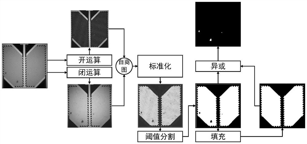
[0032] Electrode contamination detection methods include:

[0033] Step 1: Preprocessing the electrode image obtained by the camera to obtain the grayscale image of the electrode.

[0034] Preprocess the image. If the image is a color image, according to experience, the general electrode part color is FPC yellow, metal silver, and the background is generally black or circuit board green, red, yellow, blue. Therefore, when encountering a color image, use the dark channel prior method to take the minimum value for the corresponding position components of the three channels to obtain an image I with stronger contrast:

[0035] I(x,y)=min(R(x,y),G(x,y),B(x,y))

[0036] Among them, I(x, y) is the value of the electrode grayscale image I at the position (x, y), R(x, y), G(x, y), B(x, y) represent the position (x, y) respectively , red, green and blue channel component values ​​of the pixel at y)

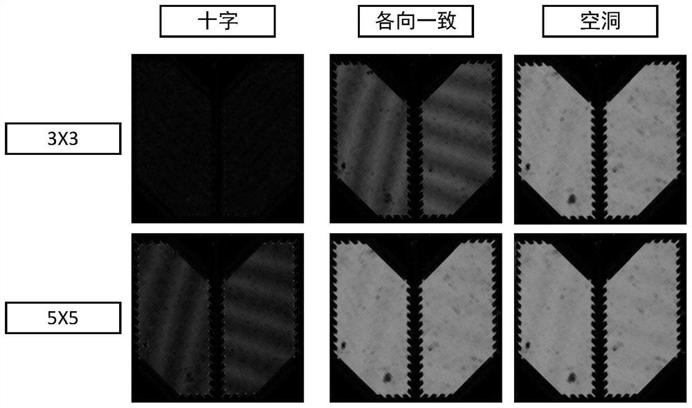
[0037] Step 2: Construct a morphological operator template set, and perform opening...


PUM


Abstract

The invention discloses an electrode dirt detection method. The method comprises the following steps: preprocessing an electrode image to obtain an electrode grayscale image; according to templates inthe morphological operator template set, carrying out opening operation and closing operation on the electrode grayscale image to obtain an electrode foreground image and an electrode background image; performing autoquotient graph operation by utilizing the electrode foreground image and the electrode background image to obtain initial autoquotient graph data; 4, establishing an optimal auto-quotient graph data selection model, obtaining optimal auto-quotient graph data, and performing deviation standardization processing on the optimal auto-quotient graph data; performing thresholding processing on the standardized auto-quotient graph data to obtain a connected domain image; and extracting an outer contour of the connected domain image and filling to obtain mask data, and performing exclusive-OR operation on the mask data and the connected domain image to obtain a dirt segmentation result. By means of the invention, electrode dirt segmentation can be achieved, the adaptability to illumination changes is high, the workload of manual parameter adjustment is reduced, the calculation efficiency is high, and the detection precision is high.

Description

technical field [0001] The invention relates to the technical field of electrode detection, in particular to an electrode defect detection method. Background technique [0002] An electrode is a comb-shaped sensor element interspersed by the two ends of the electrode. Usually, the two poles of the electrode are passed into a square wave for reactance-based calculations. The electrodes need to be inspected and cleaned during production, but in some cases the electrodes cannot be packaged well during use, such as glass substrates, etc. Since ordinary dirt can absorb part of electromagnetic waves, once the electrodes come into contact with dirt without protective measures, problems such as short circuit and signal attenuation will occur. [0003] Currently, methods for detecting soiling include two types. One is designed around the MURA (display unevenness) detection requirements of liquid crystal panels and other products, and needs to provide environments with special requi...

Claims


Application Information

Patent Timeline
Patent Type & Authority Applications(China)
IPC IPC(8): G06T7/00G06T7/187G06T7/136G06T7/13G06K9/62
CPCG06T7/0004G06T7/187G06T7/136G06T2207/10004G06T2207/30108G06T7/13G06V10/751
Inventor 刘玲杨静
Owner 郑州迈拓信息技术有限公司
Why Eureka
Try Eureka