
A coherent optical receiving device and optical signal demodulation device

A receiving device and coherent optical technology, which is applied in the field of coherent optical communication, can solve the problems that the frequency mixing device cannot work normally, the coherent optical transmission technology generally has poor adaptability, and the coherent optical transmission technology cannot be applied, etc.

Inactive Publication Date: 2021-11-19
HUAWEI TECH CO LTD
View PDF17 Cites 0 Cited by
  • Summary
  • Abstract
  • Description
  • Claims
  • Application Information

AI Technical Summary

Problems solved by technology

[0003] At present, the frequency mixing devices used in the industry (such as conventional coherent optical mixing units and frequency mixers) need to input local oscillator light with a fixed polarization state, because such networks cannot satisfy such requirements in data center networks (DCN) and other networks. The special requirements on the polarization state of the local oscillator cause the current mixing device in the industry to fail to work normally, and ultimately make the coherent optical transmission technology unable to be applied to DCN and other network application scenarios, resulting in poor general adaptability of the coherent optical transmission technology

Method used


Image

  • A coherent optical receiving device and optical signal demodulation device
  • A coherent optical receiving device and optical signal demodulation device
  • A coherent optical receiving device and optical signal demodulation device

Examples


Embodiment Construction

[0032] Embodiments of the present application are described below in conjunction with the accompanying drawings. Apparently, the described embodiments are only part of the embodiments of the present application, not all of the embodiments. Those of ordinary skill in the art know that, with the development of technology and the emergence of new scenarios, the technical solutions provided in the embodiments of the present application are also applicable to similar technical problems.

[0033] Embodiments of the present application provide a coherent optical receiving device and an optical signal demodulation device, which are used to eliminate the special requirement of the coherent optical receiving device on the fixed polarization state of input local oscillator light, and improve the universal adaptability of coherent optical transmission technology.

[0034] The term "and / or" appearing in this application may be an association relationship describing associated objects, indic...


PUM


Abstract

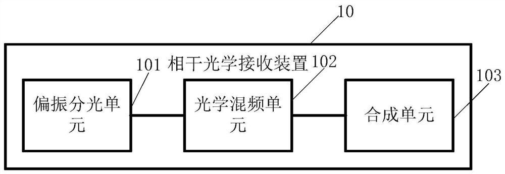
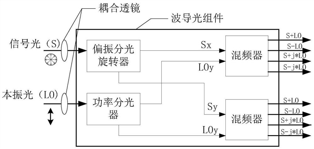
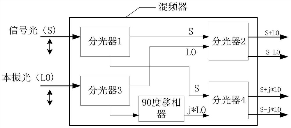
Embodiments of the present application provide a coherent optical receiving device and an optical signal demodulation device, which are used to eliminate the special requirement of the coherent optical receiving device on the fixed polarization state of input local oscillator light, and improve the universal adaptability of coherent optical transmission technology. The application method includes: a polarization splitting unit, an optical mixing unit and a synthesis unit, the polarization splitting unit is connected to the input end of the optical mixing unit, and the synthesis unit is connected to the output end of the optical mixing unit; the polarization splitting unit is used for: receiving any polarized local oscillator light, and decompose the received local oscillator light to obtain the first polarized light with orthogonal polarization state; the optical mixing unit is used to: combine the first polarized light with the second polarized light Mixing, after mixing, the optical output value is synthesized in the unit, and the second polarized light is the polarization state orthogonal polarized light obtained by decomposing the signal light; the combining unit is used to: combine every two The road light is synthesized into one output.

Description

technical field [0001] The present application relates to the technical field of coherent optical communication, in particular to a coherent optical receiving device and an optical signal demodulation device. Background technique [0002] Coherent optical transmission technology has the advantages of large transmission capacity and long distance, and is widely used. At the receiving end of the coherent optical communication system, the local oscillator light and the signal light are simultaneously input into the mixing device for mixing, and the output light after mixing is converted into an electrical signal, which can be obtained by sampling, analog-to-digital conversion and digital signal processing. The amplitude and phase information of the signal light, so as to realize the decoding function. [0003] At present, the frequency mixing devices used in the industry (such as conventional coherent optical mixing units and mixers) need to input local oscillator light with a...

Claims


Application Information

Patent Timeline
Patent Type & Authority Patents(China)
IPC IPC(8): H04B10/61
CPCH04B10/6151H04B10/64H04B10/614H04B10/612
Inventor 赵平李良川桂韬
Owner HUAWEI TECH CO LTD
Learn More