Compressor
A compressor and rotor technology, applied in the field of compressors, can solve problems such as system efficiency reduction, and achieve the effect of reducing oil discharge and suppressing flow path resistance.
- Summary
- Abstract
- Description
- Claims
- Application Information
AI Technical Summary
Problems solved by technology
Method used
Image

Examples
Embodiment 1
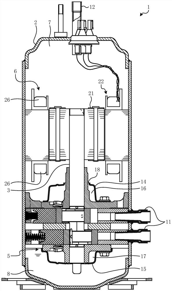
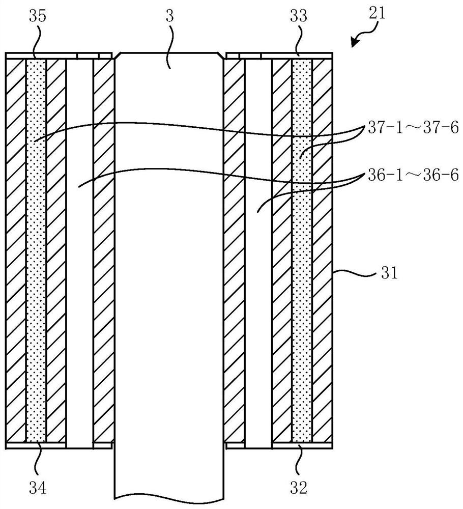
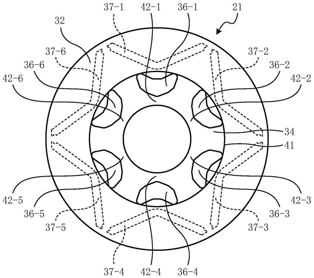
[0052] Effects of the compressor 1 of the first embodiment
[0053] The compressor 1 of Embodiment 1 includes: a rotor 21; a stator 22 that rotates the rotor 21 around a rotation axis; a compressor unit 5 that compresses refrigerant by the rotation of the rotor 21; and a container 2 that houses the rotor 21. , the stator 22, and the internal space 7 of the compressor part 5. The rotor 21 includes: a rotor core 31 formed with a plurality of through-holes 36-1 to 36-6 through which the refrigerant flows, and the plurality of through-holes 36-1 to 36-6 have curved portions facing the rotation axis. The V-shaped cross-section protruding in the direction; the lower rotor end plate 32 (first end plate), which covers the lower rotor end surface 34 (first end surface) in the rotor core 31, and the lower rotor end surface 34 (first end surface) 1 end surface) of the two ends where the through holes 36-1 to 36-6 are formed, one end closer to the compressor part 5; and the upper rotor e...
PUM
 Abstract
Description
Claims
Application Information
 - R&D
- Intellectual Property
- Life Sciences
- Materials
- Tech Scout
- Unparalleled Data Quality
- Higher Quality Content
- 60% Fewer Hallucinations
Browse by: Latest US Patents, China's latest patents, Technical Efficacy Thesaurus, Application Domain, Technology Topic, Popular Technical Reports.
© 2025 PatSnap. All rights reserved.Legal|Privacy policy|Modern Slavery Act Transparency Statement|Sitemap|About US| Contact US: help@patsnap.com