Eureka AIR delivers breakthrough ideas for toughest innovation challenges, trusted by R&D personnel around the world.

Drying device for food processing

A drying device and food processing technology, applied in drying, drying machine, food preservation and other directions, can solve the problems of uneven drying, inconvenient material turning over, etc., and achieve the effect of uniform drying effect

Inactive Publication Date: 2020-10-30
马迎锋
View PDF1 Cites 2 Cited by
  • Summary
  • Abstract
  • Description
  • Claims
  • Application Information

AI Technical Summary

Problems solved by technology

The drying device for food processing in the above-mentioned patent has the following disadvantages: it is inconvenient to turn over the material during use, resulting in uneven drying

Method used


Image

  • Drying device for food processing
  • Drying device for food processing
  • Drying device for food processing

Examples


Embodiment 1

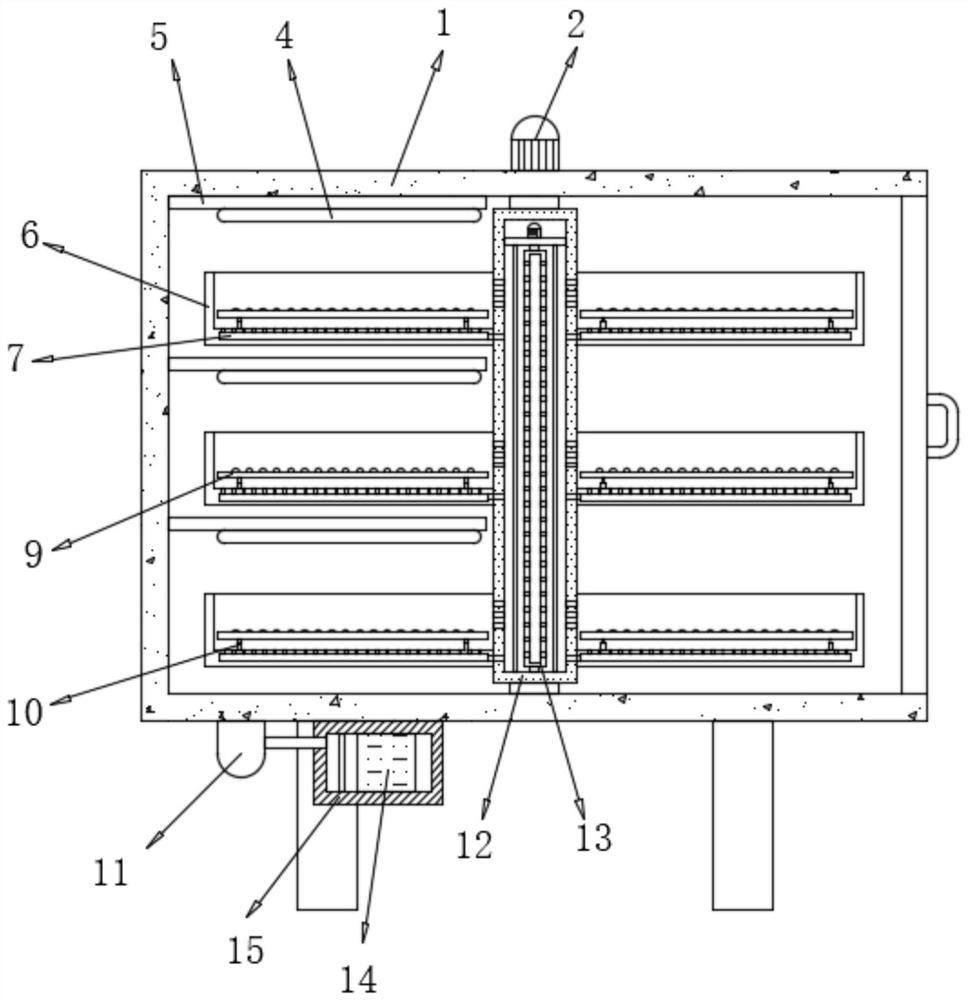
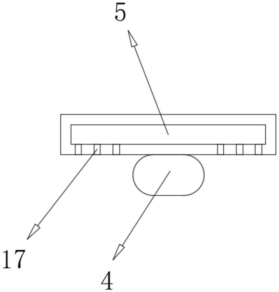
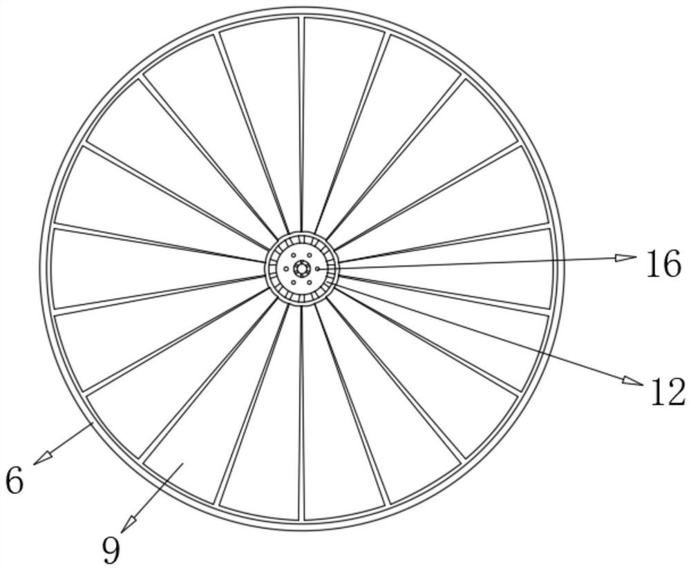
[0027] refer to Figure 1-5 , a drying device for food processing, comprising a box body 1, a box door is hinged on one side of the box body 1, a first drive motor 2 is connected to the top outer wall of the box body 1 through fastening bolts, and the first drive motor 2 The output shaft of the rotating shaft 12 is connected with a rotating shaft 12 through fastening bolts, and the outer peripheral wall of the rotating shaft 12 is connected with uniformly distributed drying tanks 6 through fastening bolts, and the outer peripheral wall of the rotating shaft 12 is provided with evenly distributed third air outlet holes. The opening position of the air hole corresponds to the position of the drying tank 6. The bottom inner wall of the drying tank 6 is connected with the electric telescopic rod 10 by fastening bolts, and the tops of two adjacent electric telescopic rods 10 are connected with the same electric telescopic rod 10 by fastening bolts. One placed screen 9, and the plac...

Embodiment 2

[0036] refer to Figure 6 , a drying device for food processing. Compared with Embodiment 1, the inner wall of the drying tank 6 is connected with the second buffer net plate 8 evenly distributed by the spring, and the outer wall of the rotating shaft 12 is connected by the spring. There are evenly distributed first buffer screens 3 , and the positions of the first buffer screens 3 correspond to the positions of the second buffer screens 8 .

[0037] Working principle: when the material rolls with the inclination of the placed screen 9, the spring, the first buffer screen 3, and the second buffer screen 8 cushion and damp the material, and at the same time, the first buffer screen 3 prevents the material from falling out of the third The pores are clogged.


PUM


Abstract

The invention discloses a drying device for food processing. The drying device comprises a box body, a box door is hinged to one side of the box body. A first driving motor is arranged on the outer wall of the top of the box body; a rotating shaft is arranged on an output shaft of the first driving motor; drying grooves which are evenly distributed are formed in the outer wall of the circumferenceof the rotating shaft, third air outlet holes which are evenly distributed are formed in the outer wall of the circumference of the rotating shaft, the opening positions of the third air outlet holescorrespond to the positions of the drying grooves, electric telescopic rods are arranged on the inner walls of the bottoms of the drying grooves, and the same placing net plate is arranged at the tops of every two adjacent electric telescopic rods. The inclination angle of the placing net plate can be adjusted through the electric telescopic rod, materials roll and turn over towards the rotatingshaft when inclining towards the rotating shaft along with the placing net plate, or the materials roll and turn over away from the rotating shaft when inclining away from the rotating shaft along with the placing net plate, the materials are turned over conveniently, and it is guaranteed that drying is more uniform.

Description

technical field [0001] The invention relates to the technical field of food processing, in particular to a drying device for food processing. Background technique [0002] In food processing, it is often necessary to dry food to reduce the water content of food and extend its shelf life. The current drying devices for food processing generally have a fixed structure, and the food to be dried is placed on the tray without moving, and then directly heated and dried, which has the problems of uneven drying and poor effect. [0003] After retrieval, the Chinese Patent Publication No. is CN209214269U, which discloses a drying device for food processing, including a drying device shell, and a motor cavity, a food drying cavity and a residual temperature cavity are respectively arranged in the drying device shell, and the motor The cavity is located on the lower side of the food drying cavity and the residual temperature cavity, and the residual temperature cavity is located outsi...

Claims


Application Information

Patent Timeline
IPC IPC(8): A23L3/28A23L3/40A23L5/20F26B11/18F26B21/04F26B25/04F26B25/18
CPCA23L3/28A23L3/40A23L5/20F26B11/18F26B21/001F26B21/003F26B21/004F26B21/04F26B25/04F26B25/18
Inventor 马迎锋
Owner 马迎锋
Why Eureka
Eureka Blog
Learn More