
A short cap nailer

A short cap and holder technology, applied in the field of short cap nail holders, can solve the problems of unstable clamping, increased wound area, unstable clamping, etc., achieve rapid assembly and disassembly, reduce wound area, reduce The effect of surgery time

Active Publication Date: 2021-09-21
天衍医疗器材有限公司
View PDF6 Cites 0 Cited by
  • Summary
  • Abstract
  • Description
  • Claims
  • Application Information

AI Technical Summary

Problems solved by technology

[0003] In some prosthesis replacement operations, it is necessary to use short cap nails to fix the prosthesis on the human body, or use short cap nails to fix surgical tools. Beat and press down to fix the prosthesis or tool. In the existing operation, the doctor usually clamps the short cap nail with a hemostat, and then knocks and presses down the short cap nail with a knocking tool. The clamping is unstable and there is a certain defect:
[0004] 1. Using hemostats to hold short cap nails during surgery will take up a lot of space and interfere with soft tissues. There is a risk of increased trauma area and slippage leading to injury, which increases the hidden danger of surgical infection and surgical risk of failure;
[0005] 2. If the short cap nails fail to be installed or become loose for a long time, the short cap nails need to be removed and replaced. At this time, new tools are needed to remove the short cap nails. If the short cap nails are bent and damaged during the removal process, it will increase difficulty of removal;
[0006] 3. Use the hemostat to clamp the short-cap nail, resulting in unstable clamping, increased clamping difficulty, increased percussion difficulty, increased nail insertion time, and increased surgical risk;

Method used


Image

  • A short cap nailer
  • A short cap nailer
  • A short cap nailer

Examples


Embodiment

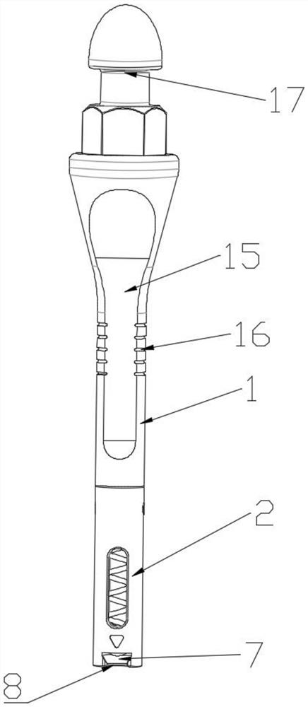
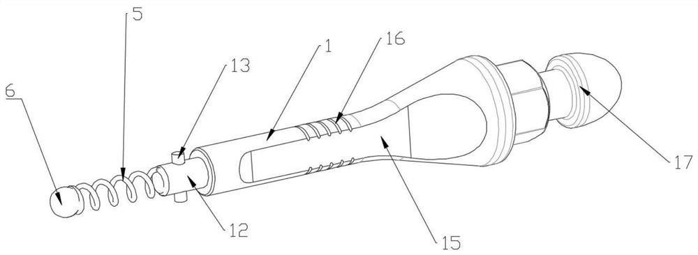
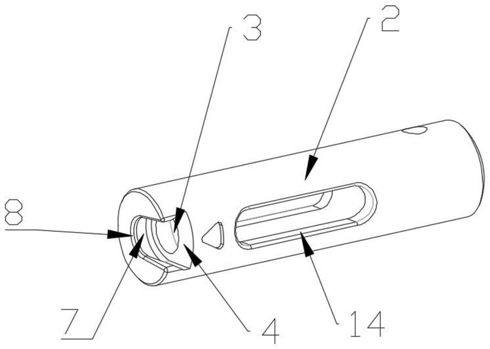
[0036] Example: See Figure 1 ~ 6In the present invention, a short cap nail holder, comprising a holder body 1, the holder body 1 is a columnar structure, is used for man-hand grasp or and a universal handle connection, and the front end of the holder body 1 is provided with a clamping column 2, clip. The column 2 is a columnar structure for clamping the short cap nail, and the through hole 3 is provided in the clamping column 2, and the through hole 3 is a cylindrical space in the inside of the column 2, and the holding column 2 is used to accommodate the spring 5. And pressure ball 6, one end of the through hole 3 is provided with inward convex 4, the inner fracture convex 4 causes the through hole 3 to form a certain degree of receipts, for placing the opposite ball 6, so that the opposing ball 6 does not take off The holes 3, the through hole 3 is provided with a spring 5, and the spring 5 is given a preload force, the through hole 3 and the inner conversion 4 corresponding to ...


PUM


Abstract

The invention discloses a short cap nail holder, comprising a holder body, a clamping column is arranged at the front end of the holder body, a through hole is arranged in the clamping column, and the through hole is far away from an end of the holder body An inner edge protrusion is provided, a spring is arranged in the through hole, a pressing ball is arranged at a position corresponding to the through hole and the inner edge protrusion, and a clamping groove is arranged at the end of the clamping column far away from the holder body. The clamping groove is trumpet-shaped, the through hole communicates with the side wall of the clamping groove, and the side of the clamping column close to the clamping groove is provided with a nail entry opening, and the clamping groove and the nail entry opening pass through the clip The side of the holding column; the cooperation of the clamping groove and the pressure ball in the present invention makes the disassembly and assembly of the short cap nail very simple, and realizes rapid assembly and disassembly, and when the short cap nail is installed, there is instantaneous friction with the pressure ball, Vibration and sound are generated, and the sound can be used to judge whether the short cap nail is clamped successfully, which greatly facilitates the doctor's judgment and reduces the operation time.

Description

Technical field [0001] The present invention relates to the nail field, specifically a short cap nail holder. Background technique [0002] Surgery is to discharge lesions through surgical equipment or surgical instruments, into human tissue, extrovers lesions, change the process of constructing or implanting foreign objects. Prosthetic replacement surgery is to use the tool to install the artificial prosthesis in the human body to replace the process of lesions and bones. [0003] In some prosthetic replacement surgery, it is necessary to secure the prosthesis in the human body with a short cap nail, or use a short cap nail to fix the surgical tool. The specific fixation process is to clamp the short cap, and the tool will stop Tap the lower pressure, fix the prosthesis or tool, existing surgery, the doctor usually uses the hemostasis clamping short cap nail, and then uses a knocking tool to hit the short-capped push, clamatically, there is a certain defect: [0004] First, use ...

Claims


Application Information

Patent Timeline
Patent Type & Authority Patents(China)
IPC IPC(8): A61B17/88A61B17/92
CPCA61B17/88A61B17/92
Inventor 王楠毛联甲
Owner 天衍医疗器材有限公司
Learn More