
Control system for rotating speed of stirring device

A technology of rotating speed control and stirring device, which is applied to control/adjustment systems, mixers with rotating stirring devices, and accessories of mixers, etc.

Inactive Publication Date: 2020-10-30
广州狸园科技有限公司
View PDF10 Cites 1 Cited by
  • Summary
  • Abstract
  • Description
  • Claims
  • Application Information

AI Technical Summary

Problems solved by technology

[0004] In the process of realizing the present invention, the inventor found that at least the following problems in the prior art have not been solved: the existing stirring device is inconvenient to disassemble and assemble when it is in use, which makes it difficult to clean the inside of the housing, and its The mixing effect can be further improved

Method used


Image

  • Control system for rotating speed of stirring device
  • Control system for rotating speed of stirring device
  • Control system for rotating speed of stirring device

Examples


Embodiment Construction

[0041]In describing the present invention, it should be understood that the terms "center", "longitudinal", "transverse", "upper", "lower", "front", "rear", "left", "right", " The orientations or positional relationships indicated by "vertical", "horizontal", "top", "bottom", "inner" and "outer" are based on the orientations or positional relationships shown in the drawings, and are only for the convenience of describing the present invention and Simplified descriptions, rather than indicating or implying that the device or element referred to must have a particular orientation, be constructed and operate in a particular orientation, and thus should not be construed as limiting the invention. In addition, the terms "first", "second", etc. are used for descriptive purposes only, and should not be understood as indicating or implying relative importance or implicitly specifying the quantity of the indicated technical features. Thus, a feature defined as "first", "second", etc. m...


PUM


Abstract

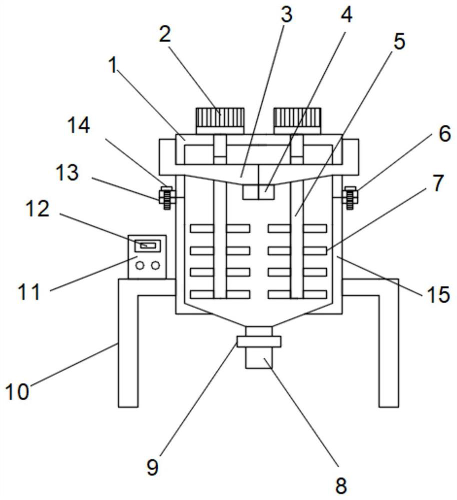
The invention relates to the technical field of stirring devices and discloses a control system for the rotating speed of a stirring device. The control system comprises a box body a and a box body b,wherein the bottom of the box body a is open; rotating motors are fixedly mounted on the two sides of the top end of the box body a; the heads of motor shafts of the two rotating motors movably penetrate through the top end of the box body a, shaft rods are fixedly installed on the heads of the two motor shafts, and a plurality of stirring rods are fixedly installed at the lower ends of the two sides of each shaft rod; and feeding pipes are fixedly connected to the left side and the right side of the box body a in a penetrating mode. According to the invention, the two rotating motors and a motor rotating speed control module are arranged; when the system is used, materials can be fed through the feeding pipes, then the two rotating motors are started while the materials fall into the boxbody b from discharging ports, the two rotating motors drive the shaft rods to rotate at different rotating speeds, and therefore, when the materials on the two sides of the box body b are stirred, adifferential speed exists and the stirring effect in the prior art is thus effectively improved.

Description

technical field [0001] The invention relates to the technical field of stirring devices, in particular to a stirring device rotation speed control system. Background technique [0002] The so-called paint is coated on the surface of the object to be protected or decorated, and can form a continuous film firmly attached to the object to be coated, usually based on resin, oil, or emulsion, with or without adding pigments, fillers, adding Corresponding additives are viscous liquids prepared with organic solvents or water. In the coating production process, raw materials usually need to be blended, and the blending operations are mostly carried out in the batching tank. When mixing the paint, the raw materials are first According to the order of the recipe, put them into the batching tank in turn, and stir the raw materials in the batching tank. When the existing batching tank is stirred, artificial stirring is required, but the mixing effect of artificial stirring is not good,...

Claims


Application Information

Patent Timeline
IPC IPC(8): B01F7/16B01F7/18B01F15/00B01F15/06G05D27/02
CPCG05D27/02B01F27/85B01F27/90B01F35/2115B01F35/2215B01F35/91B01F2101/30
Inventor 胡日媛
Owner 广州狸园科技有限公司
Learn More