Supercharge Your Innovation With Domain-Expert AI Agents!

Thermostatic bath and control method thereof

A constant temperature control and control method technology, which is applied to chemical instruments and methods, laboratory appliances, heating or cooling equipment, etc., can solve the problems of long waiting time, high energy consumption, frequent heating and cooling, etc., and achieve short waiting time and low energy consumption. The effect of low energy consumption and high work efficiency

Active Publication Date: 2020-10-30
山东磐然仪器集团有限公司
View PDF30 Cites 0 Cited by
  • Summary
  • Abstract
  • Description
  • Claims
  • Application Information

AI Technical Summary

Problems solved by technology

[0007] The purpose of the present invention is to provide a constant temperature tank and its control method to solve the problems of frequent heating and cooling, long waiting time and high energy consumption when the constant temperature tank is cycled between different temperature points

Method used


Image

  • Thermostatic bath and control method thereof
  • Thermostatic bath and control method thereof

Examples


Embodiment 1

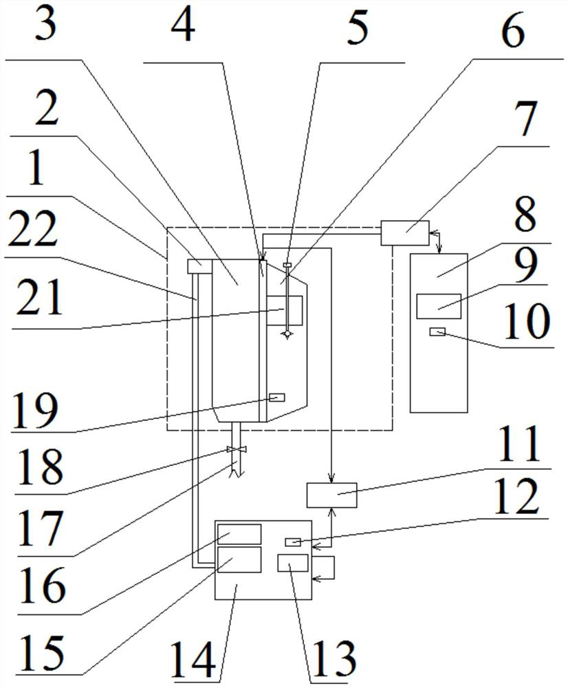
[0041] Such as figure 1 , a constant temperature tank, including a constant temperature tank body 1, and also includes a heating chamber 8 and a cooling chamber 14 communicated with the constant temperature tank body 1, and the heating chamber 8 passes through the second bidirectional pump 7 or at least two unidirectional pumps The combination introduces or exports the circulating high-temperature working medium into the constant temperature tank 1, and the refrigeration chamber 14 introduces or exports the circulating low temperature working medium into the constant temperature tank 1 through the first two-way pump 11 or a combination of at least two unidirectional pumps. working medium.

[0042] Working process: when switching between high and low temperature, turn on the second two-way pump 7 to transport the high-temperature working medium in the working chamber 3 to the heating chamber 8, then turn off the second two-way pump 7, turn on the first two-way pump 11, and turn...

Embodiment 2

[0045] Such as figure 1 , On the basis of Embodiment 1, a third heater 9 and a third temperature control sensor 10 are arranged in the heating chamber 8 . It plays the role of pre-heating and pre-controlling the high-temperature working medium in the heating chamber 8.

Embodiment 3

[0047] Such as figure 1 , On the basis of Embodiment 1, a second heater 16 , a refrigeration evaporator 15 and a second temperature control sensor 12 are arranged in the refrigeration chamber 14 . The second heater 16 is used for heating the low-temperature working medium, the refrigeration evaporator 15 is used for cooling the low-temperature working medium, and the second temperature control sensor 12 is mainly used for testing the heating and cooling speed and the temperature of the low-temperature working medium.


PUM


Abstract

The invention discloses a thermostatic bath and a control method thereof. The invention belongs to the technical field of liquid thermostatic baths. The invention particularly relates to the technicalfield of liquid thermostatic bath temperature control, and aims to solve the problem of frequent rise and drop in temperature, long waiting time and high energy consumption when a thermostatic tank circulates between different temperature points; the thermostatic bath comprises a thermostatic bath body, and further comprises a heating cavity and a refrigerating cavity which are communicated withthe thermostatic bath body, the heating cavity imports or exports a circularly flowing high-temperature working medium into or out of the thermostatic bath body through a second two-way pump, and therefrigerating cavity imports or exports a circularly flowing low-temperature working medium into or out of the thermostatic bath body through a first two-way pump. Through the arrangement of the heating cavity, the refrigerating cavity, the first two-way pump and the second two-way pump on one side of the thermostatic bath body, cold and hot media in the thermostatic bath body can be rapidly replaced while it is guaranteed that the media in the thermostatic bath body are uniform and constant in temperature, the intermediate waiting time is short, energy consumption is low, and the working efficiency is high.

Description

technical field [0001] A constant temperature tank and a control method thereof belong to the technical field of liquid constant temperature tanks, and specifically relate to the technical field of liquid constant temperature tank temperature control. Background technique [0002] Liquid constant temperature bath is the most commonly used constant temperature source in the field of temperature measurement. It is widely used in the calibration and testing of various temperature sensors, temperature transmitters, temperature switches and other temperature sensitive components. When it works, the heating or cooling capacity is controlled by a dedicated temperature controller to keep the temperature of the working medium inside constant, thus providing the necessary constant temperature environment for temperature calibration. Generally used liquid constant temperature tank fluctuation range is about 0.1 ℃ / 10min. [0003] The constant temperature bath is one of the commonly u...

Claims


Application Information

Patent Timeline
IPC IPC(8): B01L7/00
CPCB01L7/00B01L2200/147
Inventor 徐军董卓郭沈辉乔文田
Owner 山东磐然仪器集团有限公司
Features
  • R&D
  • Intellectual Property
  • Life Sciences
  • Materials
  • Tech Scout
  • Unparalleled Data Quality
  • Higher Quality Content
  • 60% Fewer Hallucinations
Learn More