Construction waste treatment device
A processing device and construction waste technology, applied in grain processing, construction waste recycling, recycling technology, etc., can solve the problems of large volume, large space occupation, and increased construction waste transportation costs, achieving good continuity and high efficiency Effect
- Summary
- Abstract
- Description
- Claims
- Application Information
AI Technical Summary
Problems solved by technology
Method used
Image

Examples
specific Embodiment approach 1
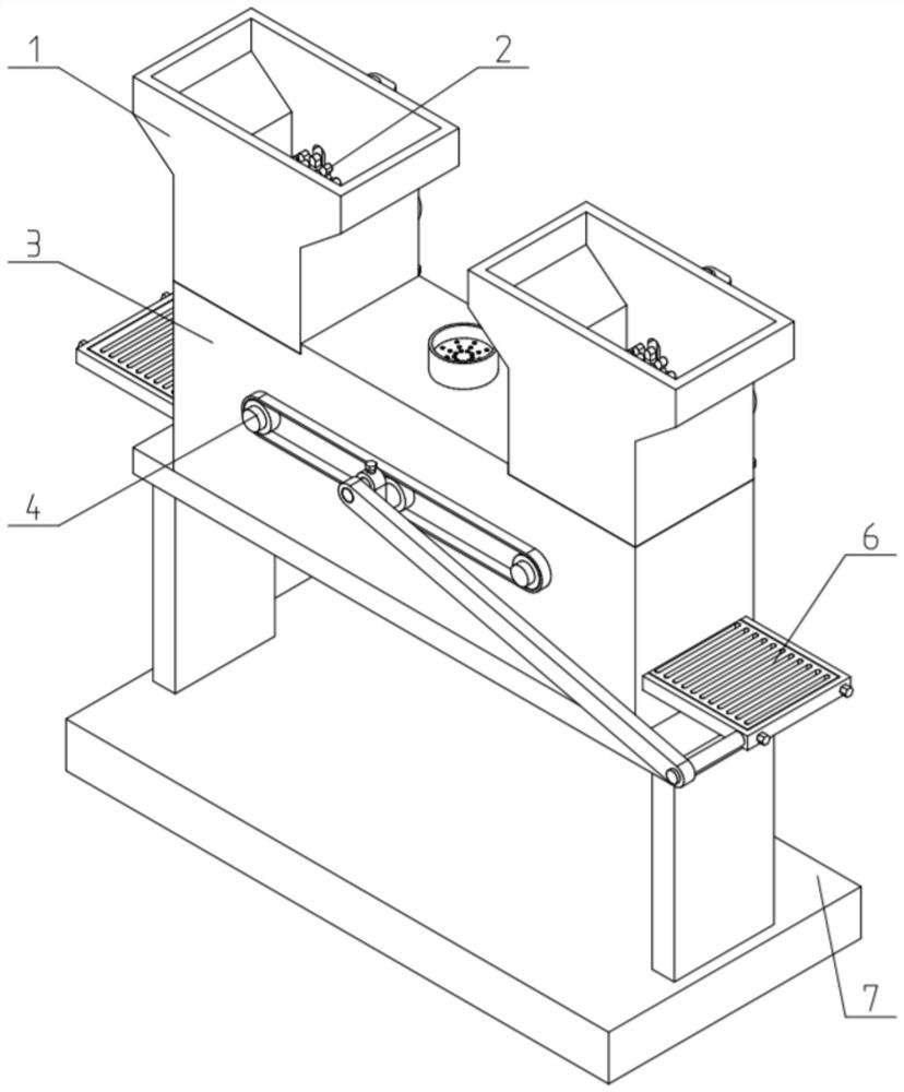
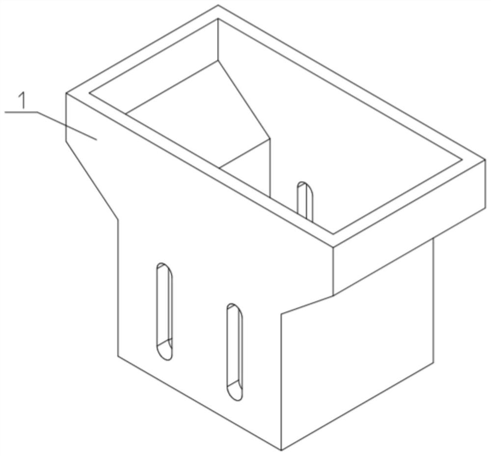
[0037] like Figure 1-11 As shown, the construction waste treatment device includes a feeding crushing box 1, a crushing and crushing mechanism 2, a mixing crushing box 3, a stirring and crushing mechanism 4, a driving mechanism 5, a screening device 6 and a frame 7. The feeding crushing box 1 is provided with two, the two feed crushing boxes 1 are relatively fixedly connected to both ends of the top surface of the mixing and crushing box 3; the mixing and crushing box 3 is fixedly connected to the frame 7; The feeding crushing box 1 is respectively connected with a crushing and crushing mechanism 2; the mixing and crushing box 3 is connected with the stirring and crushing mechanism 4; the driving mechanism 5 is connected with the mixing and crushing box 3; The driving mechanism 5 is drivingly connected to the stirring and crushing mechanism 4 and the two crushing and crushing mechanisms 2; the stirring and crushing mechanism 4 is drivingly connected to the screening device 6 ...
specific Embodiment approach 2
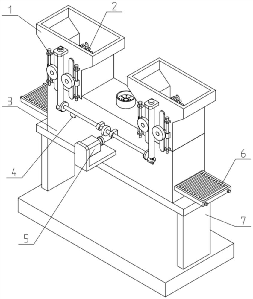
[0038] like Figure 1-11 As shown, the drive mechanism 5 includes a servo motor 501, a first worm 502, a first worm wheel 503, a first shaft 504, a first shaft seat 505 and a friction transmission wheel 506; the servo motor 501 is fixedly connected to the on the mixing and crushing box 3; the output shaft of the servo motor 501 is connected to the first worm 502 through a coupling; the first worm 502 is meshed and connected to the first worm wheel 503; the first worm wheel 503 Fixedly connected in the middle of the first shaft 504; the first shaft 504 is rotatably connected to the two first shaft seats 505; the first shaft seats 505 are fixedly connected to the mixing and crushing box 3 ; The two ends of the first rotating shaft 504 are respectively fixedly connected to one of the friction transmission wheels 506; The stirring and crushing mechanism 4. The servo motor 501 inside the drive mechanism 5 can drive the first worm 502 to rotate after being activated. When the firs...
specific Embodiment approach 3
[0039] like Figure 1-11 As shown, the crushing mechanism 2 includes a friction linkage wheel 201, a second worm 202, a transverse seat 203, a second worm wheel 204, a rotating shaft 205, a bearing frame 206 and a crushing roller 207; the friction transmission wheel 506 is vertical The friction drive is connected to the friction linkage wheel 201; the friction linkage wheel 201 is connected to the lower end of the second worm 202; the upper end of the second worm 202 is rotatably fitted on the transverse seat 203; the transverse seat 203 is fixedly connected On the feed crushing box 1; the second worm 202 is engaged and connected to the two second worm gears 204; the two second worm gears 204 are fixedly connected to one end of the two rotating shafts 205 respectively; The two rotating shafts 205 are slidably fitted in the groove-shaped slideways and groove-shaped through holes on the inner side of the feeding crushing box 1; the two rotating shafts 205 are respectively rotata...
PUM
 Abstract
Description
Claims
Application Information
 - R&D
- Intellectual Property
- Life Sciences
- Materials
- Tech Scout
- Unparalleled Data Quality
- Higher Quality Content
- 60% Fewer Hallucinations
Browse by: Latest US Patents, China's latest patents, Technical Efficacy Thesaurus, Application Domain, Technology Topic, Popular Technical Reports.
© 2025 PatSnap. All rights reserved.Legal|Privacy policy|Modern Slavery Act Transparency Statement|Sitemap|About US| Contact US: help@patsnap.com