
Steel structure spraying facility for power transmission iron tower

A technology for spraying equipment and power transmission towers, applied in the direction of spraying devices, etc., can solve the problems of omission of steel structures, unsprayed, unfavorable subsequent use of steel structures, etc.

Active Publication Date: 2020-10-30
FUYANG SANHUAN POWER EQUIP CO LTD
View PDF10 Cites 3 Cited by
  • Summary
  • Abstract
  • Description
  • Claims
  • Application Information

AI Technical Summary

Problems solved by technology

[0005] The invention can solve the problem that when the existing equipment sprays the antirust material on the steel structure, usually only one side of the steel structure can be sprayed, and the other side of the steel structure is prone to omission, resulting in poor spraying effect of the steel structure and poor spraying effect. Unevenness is not conducive to the subsequent use of the steel structure, and the existing equipment is usually unable to accurately adjust the spraying range of the spraying mechanism when spraying the steel structure, resulting in the possibility of crossing or crossing on the steel structure after spraying Unsprayed phenomena affect the subsequent use of steel structures and other problems

Method used


Image

  • Steel structure spraying facility for power transmission iron tower
  • Steel structure spraying facility for power transmission iron tower
  • Steel structure spraying facility for power transmission iron tower

Examples


Embodiment Construction

[0026] The embodiments of the present invention will be described in detail below with reference to the accompanying drawings, but the present invention can be implemented in many different ways defined and covered by the claims.

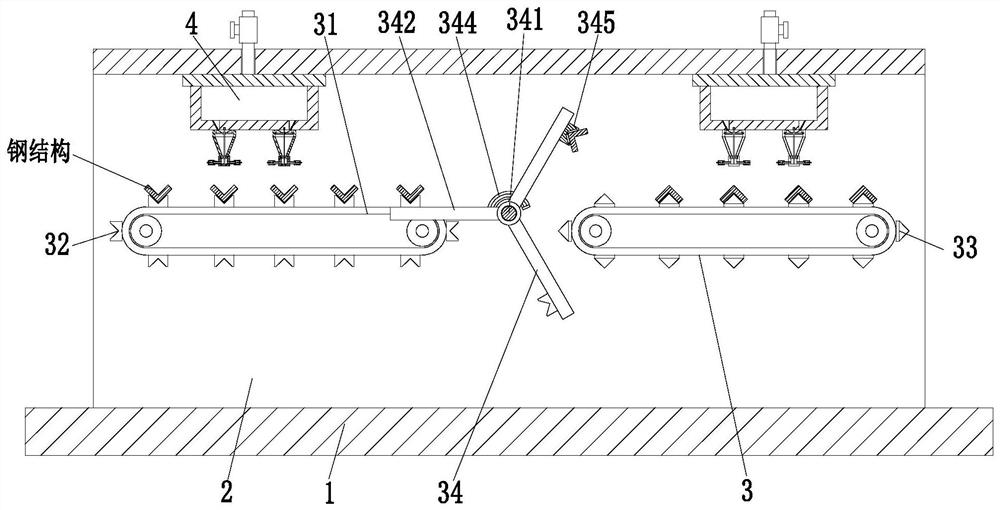
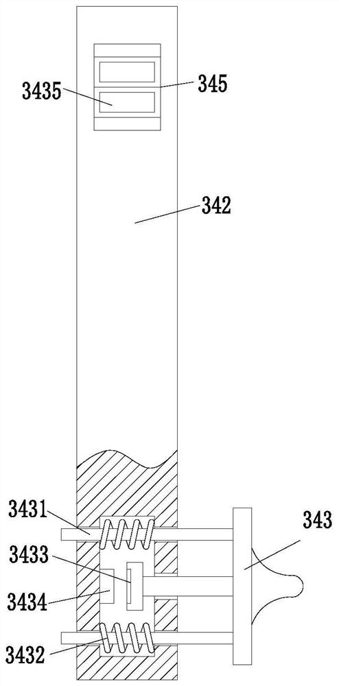
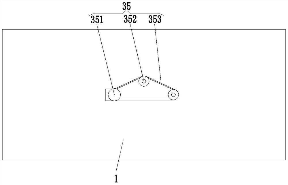
[0027] Such as Figure 1 to Figure 6 As shown, a steel structure spraying equipment for a power transmission tower includes a base plate 1, a support frame 2, a conveying device 3 and a spraying device 4, the upper end of the base plate 1 is equipped with a support frame 2, and the support frame 2 is in a U-shaped structure, supporting A conveying device 3 is installed in the middle of the frame 2, and a spraying device 4 is arranged symmetrically above the conveying device 3, and the spraying device 4 is installed on the upper end of the supporting frame 2.

[0028] The conveying device 3 includes a conveyor belt 31, a fixed seat 32, a support seat 33, an overturning mechanism 34 and a drive mechanism 35, and the conveyor belt 31 is symmetrically i...


PUM


Abstract

The invention relates to a steel structure spraying facility for a power transmission iron tower. The steel structure spraying facility for the power transmission iron tower comprises a base plate, asupporting frame, conveying devices and spraying devices. The supporting frame is installed at the upper end of the base plate, the conveying devices are installed in the middle of the interior of thesupporting frame, and the spraying devices are symmetrically arranged above the conveying devices and installed at the upper end of the interior of the supporting frame. The steel structure sprayingfacility for the power transmission iron tower can solve the problems that when an existing facility sprays rust-resisting materials to a steel structure, only one side of the steel structure can be sprayed in general, the omission phenomenon is prone to happen on the other side of the steel structure, and therefore the spraying effect of the steel structure is poor, spraying operation is not uniform, and the follow-up utilization of the steel structure is not facilitated; and when the existing facility conducts spraying processing operation on the steel structure, the spraying range of a spraying mechanism cannot be accurately adjusted in general, and therefore the phenomenon that a cross exists or a part is not sprayed is prone to exist on the sprayed steel structure, and the follow-up utilization effect of the steel structure is affected.

Description

technical field [0001] The invention relates to the field of spraying processing, in particular to a steel structure spraying equipment for power transmission iron towers. Background technique [0002] The transmission tower is the supporting point of the overhead line. One circuit is erected on the transmission tower, which is a single-circuit transmission tower, and two circuits are erected on the transmission tower, which is a double-circuit transmission tower. For a long time, my country's transmission line towers have mainly been made of hot-rolled angle steel. Compared with advanced countries in the world, the steel materials used in my country's transmission towers have a single material, a low strength value, and a small choice of materials, and the steel is easily affected by the external environment. Corrosion affects the service life of steel. [0003] At present, when the existing steel structure is sprayed, there are usually the following defects: 1. When the ex...

Claims


Application Information

Patent Timeline
IPC IPC(8): B05B13/02
CPCB05B13/0221B05B13/0292
Inventor 梅永良李义凯梅清梅玉香
Owner FUYANG SANHUAN POWER EQUIP CO LTD
Learn More