
Perforating device and perforating method of wind power blade

A technology for drilling devices and wind turbine blades, which is applied in the direction of drilling templates for workpieces, etc., can solve the problems of difficult dimensions, failure to meet the size requirements of drawings, and inability to ensure consistency, etc., to achieve the effect of reducing size errors

Pending Publication Date: 2020-10-30
TIANJIN CRRC WIND POWER BLADE ENG CO LTD
View PDF0 Cites 0 Cited by
  • Summary
  • Abstract
  • Description
  • Claims
  • Application Information

AI Technical Summary

Problems solved by technology

[0003] 1. Since the drain hole is at the tip of the blade, and the tip of the blade is curved, it is difficult to measure its size with a tape measure, and there are large errors
[0004] 2. Guaranteed two 45° included angles with the blades. The operation is completely based on the experience of the workers. It cannot meet the size requirements of the drawings and cannot guarantee consistency.
[0005] 3. If the worker is not careful when punching holes, the PS surface and SS surface of the blade will be penetrated as a whole, resulting in quality defects

Method used


Image

  • Perforating device and perforating method of wind power blade
  • Perforating device and perforating method of wind power blade
  • Perforating device and perforating method of wind power blade

Examples


Embodiment Construction

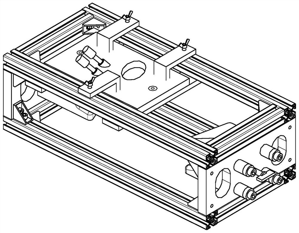
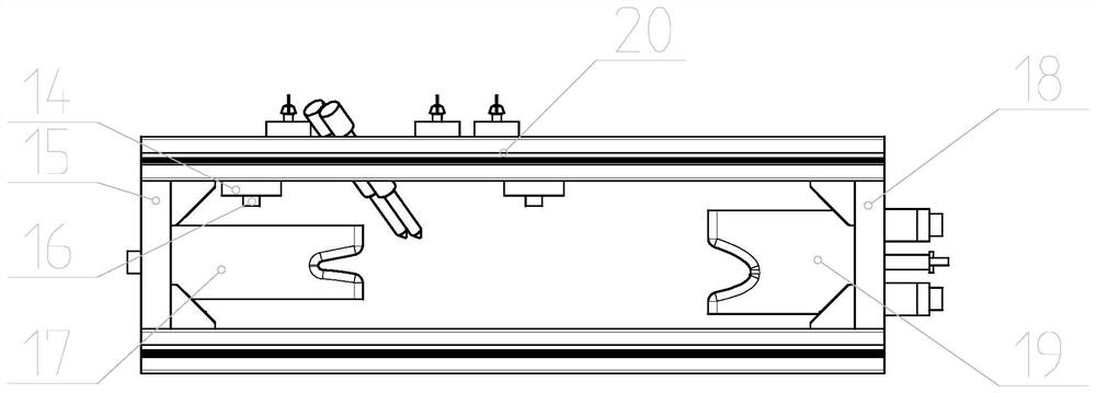
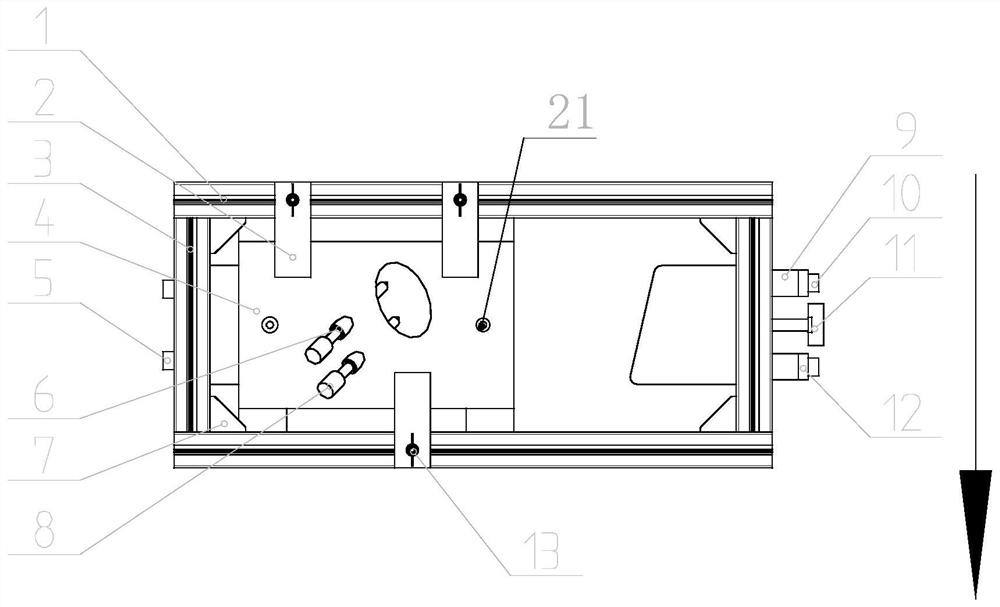
[0028] In order to enable those skilled in the art to better understand the technical solutions of the present invention, the present invention will be further described in detail below in conjunction with the accompanying drawings and preferred embodiments.

[0029] As shown in the figure, the beam 1 and the longitudinal beam 3 of the present invention form the upper frame and the lower frame of the device, the upper and lower frames are supported and connected by the first side plate 15 and the second side plate 18, and each connection point is reinforced by a corner piece 7 connection, the upper end and the middle part of the lower end of the crossbeam 1 are respectively provided with tracks for the sliding of the second wing bolt 13 and the locking bolt 16, the first side plate 15 is connected to the fixed limit plate 17 by the first bolt 5, and the second side plate 18 is connected with the accompanying limit block 19 through the unloading bolt 10, and the rectangular spri...


PUM


Abstract

The invention provides a perforating device and perforating method of a wind power blade, and relates to the field of blade perforating. The perforating device comprises a rack structure, an adjustingdevice and a perforating device. By means of the device, time wasted by hole position surveying and mapping of workers can be reduced. Size errors brought by manual measurement are reduced, and tapemeasures and marking pens are omitted. The problem of poor perforating consistency caused by personnel replacement is reduced. Penetrating damage caused to blades during perforating due to the fact that personal skills and strengths are different is reduced.

Description

technical field [0001] The invention relates to a hole punching device, in particular to a drain hole punching device and a hole punching method for wind power blades. Background technique [0002] As an indispensable structure of the blade, the drainage hole of the wind power blade plays an irreplaceable role. The blade tip of the blade is provided with a hole with a diameter of 8 mm, and forms an angle of 45° with the surface of the blade, and also forms an angle of 45° with the centerline of the blade. It is required to penetrate the SS surface of the blade without damaging the PS surface. Difficulties in this process: [0003] 1. Since the drainage hole is at the tip of the blade, and the tip of the blade is curved, it is difficult to measure its size with a tape measure, and there are large errors. [0004] 2. Guaranteed 2 included angles of 45° with the blade. The operation is completely based on the experience of the workers, which cannot meet the size requirements...

Claims


Application Information

Patent Timeline
IPC IPC(8): B23B47/28
CPCB23B47/28
Inventor 毛亚新王学花杨春燕张纯琛李良梁斌斌
Owner TIANJIN CRRC WIND POWER BLADE ENG CO LTD
Learn More