
Drilling method of single-sided board and manufactured single-sided board

A drilling method and single-panel technology, which can be used in printed circuit manufacturing, electrical components, printed circuit components, etc., and can solve problems such as product scrapping, single-panel defects, and inability to completely avoid them.

Pending Publication Date: 2022-04-12
鹤山市泰利诺电子有限公司
View PDF0 Cites 0 Cited by
  • Summary
  • Abstract
  • Description
  • Claims
  • Application Information

AI Technical Summary

Problems solved by technology

[0003] Since the electronic components need to pass through the holes on the board when they are connected to the board, if there are defects in the holes used to connect the electronic components, for example, there is a sharp edge, it will easily lead to short circuit or open circuit of the PCB, and even lead to the scrapping of the product
Therefore, in the process of preparing the PCB, the sharp edges generated by the drilling need to be strictly controlled. Taking the single-sided board as an example, before drilling the single-sided board, the copper side of the single-sided board placed on the backing board should face the First, cover the single panel with aluminum sheet, and then drill the single panel. Due to the covering effect of the aluminum plate, the height of the batch front generated by the drilling process on the copper surface of the single panel can be greatly reduced, but it is still not possible to completely Avoid the sharpening of the copper surface of the single-sided board due to drilling. As a result, the copper surface of the single-sided board still needs to be polished to remove the sharpening after drilling. The debris generated by the front can easily lead to bad

Method used


Image

  • Drilling method of single-sided board and manufactured single-sided board
  • Drilling method of single-sided board and manufactured single-sided board
  • Drilling method of single-sided board and manufactured single-sided board

Examples


Embodiment Construction

[0023] It should be noted that, in the case of no conflict, the embodiments in the present application and the features in the embodiments can be combined with each other.

[0024] It should also be noted that in this article, relational terms such as first and second etc. are only used to distinguish one entity or operation from another entity or operation, and do not necessarily require or imply that these entities or operations Any such actual relationship or order exists between. Moreover, the terms "comprising" and "comprising" not only include those elements, but also include other elements not explicitly listed, or also include elements inherent in such a process, method, article, or device. Without further limitations, an element defined by the statement "comprising..." does not exclude the presence of additional same elements in the process, method, article or device comprising said element. The terms used herein are generally commonly used terms by those skilled in ...


PUM


Abstract

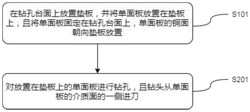
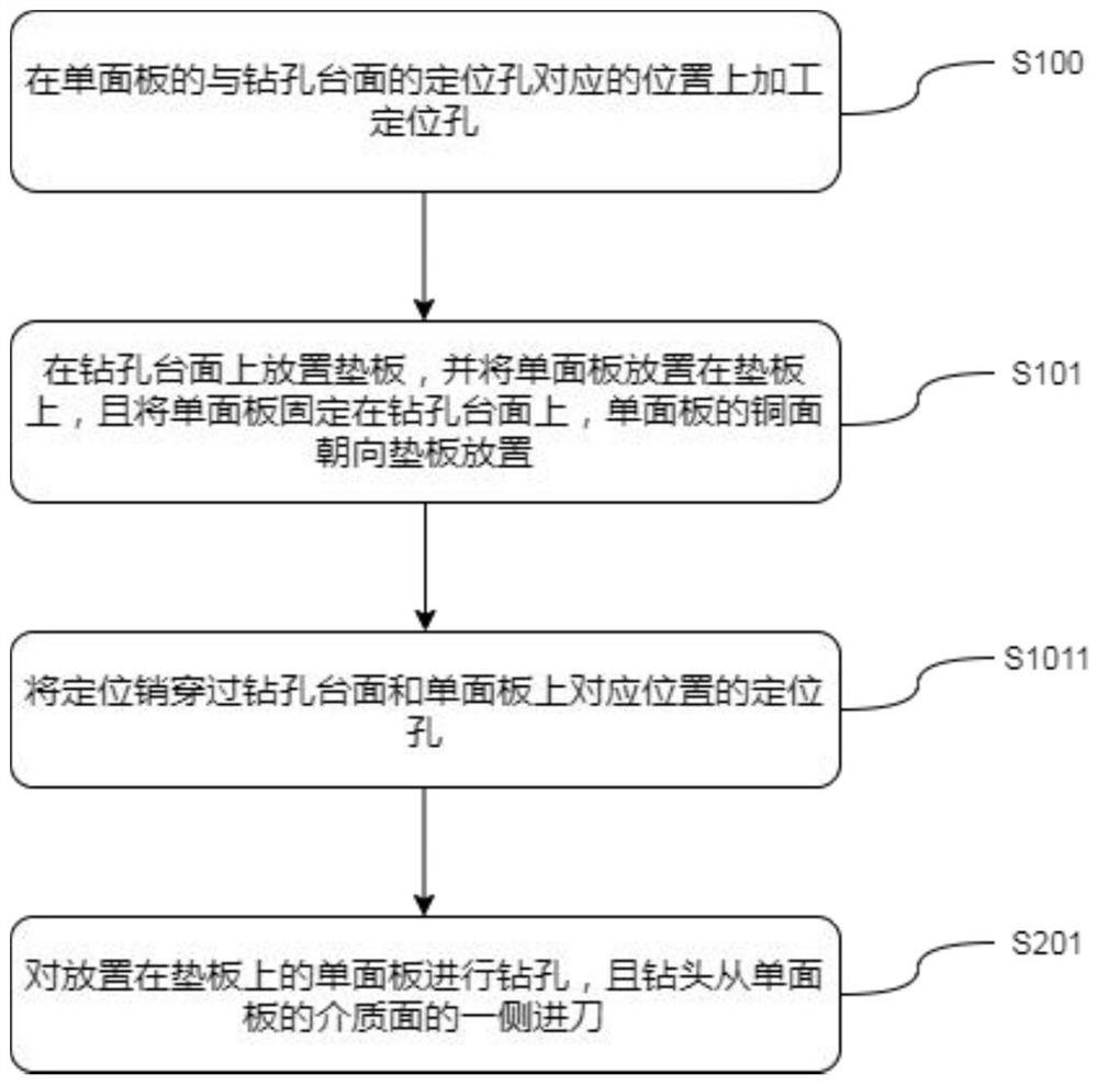
The drilling method for the single-sided board comprises the following steps that S101, a base plate is placed on a drilling table top, the single-sided board is placed on the base plate, the single-sided board is fixed to the drilling table top, and the copper face of the single-sided board faces the base plate; and S201, drilling is conducted on the single-sided board placed on the base plate, and a drill bit feeds from one side of the medium face of the single-sided board. According to the single-sided board machined through the drilling method, burrs generated after drilling are all located on the medium face of the single-sided board, and due to the fact that the medium face of the single-sided board is not provided with wires and copper, even if the burrs on the medium face of the single-sided board need to be polished subsequently, the wires are not prone to being damaged in the polishing process, and the service life of the single-sided board is prolonged. Therefore, the quality of the single-sided board after drilling is ensured. And moreover, the use of an aluminum sheet is avoided, so that the processing efficiency is improved, the quality is ensured, and the cost of a drilling procedure is greatly reduced.

Description

technical field [0001] The invention relates to a method for drilling a circuit board, in particular to a method for drilling a single panel and the obtained single panel. Background technique [0002] Printed Circuit Board (PCB for short) achieves circuit miniaturization and visualization by designing circuits on the board and connecting electronic components to the circuits on the board. For mass production of fixed circuits and optimization of electrical appliances Layout plays an important role. [0003] Since the electronic components need to pass through the holes on the board when they are connected to the board, if there are defects in the holes used to connect the electronic components, for example, there is a sharp edge, it is easy to cause a short circuit or open circuit on the PCB, and even cause the product to be scrapped. Therefore, in the process of preparing the PCB, the sharp edges generated by the drilling need to be strictly controlled. Taking the single-...

Claims


Application Information

Patent Timeline
IPC IPC(8): H05K3/00H05K1/02
Inventor 詹贵全
Owner 鹤山市泰利诺电子有限公司
Learn More