
Disc part flexible chamfering machine based on machine vision

A disk-type parts, machine vision technology, applied in the field of disk-type parts flexible chamfering machine, can solve problems such as danger, lack of flexibility, and different sizes

Pending Publication Date: 2020-10-30
苏州麻雀智能科技有限公司
View PDF0 Cites 1 Cited by
  • Summary
  • Abstract
  • Description
  • Claims
  • Application Information

AI Technical Summary

Problems solved by technology

Because there are many holes on the surface, and the size of each hole is not exactly the same, which adds a lot of difficulties to the production
The traditional artificial hole chamfering method is highly dependent on people, and the size of the chamfering cannot be controlled quantitatively. At the same time, there are certain risks in the operation process.
The traditional chamfering machine has obvious defects and insufficient flexibility, which requires precise and consistent placement of the workpiece, and the adjustment of tooling, tools, and machining paths is required during the changeover and debugging process, which takes too long

Method used


Image

  • Disc part flexible chamfering machine based on machine vision
  • Disc part flexible chamfering machine based on machine vision
  • Disc part flexible chamfering machine based on machine vision

Examples


Embodiment Construction

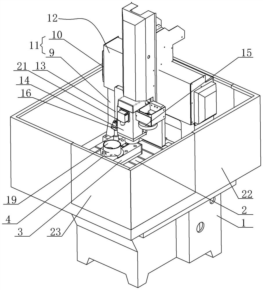
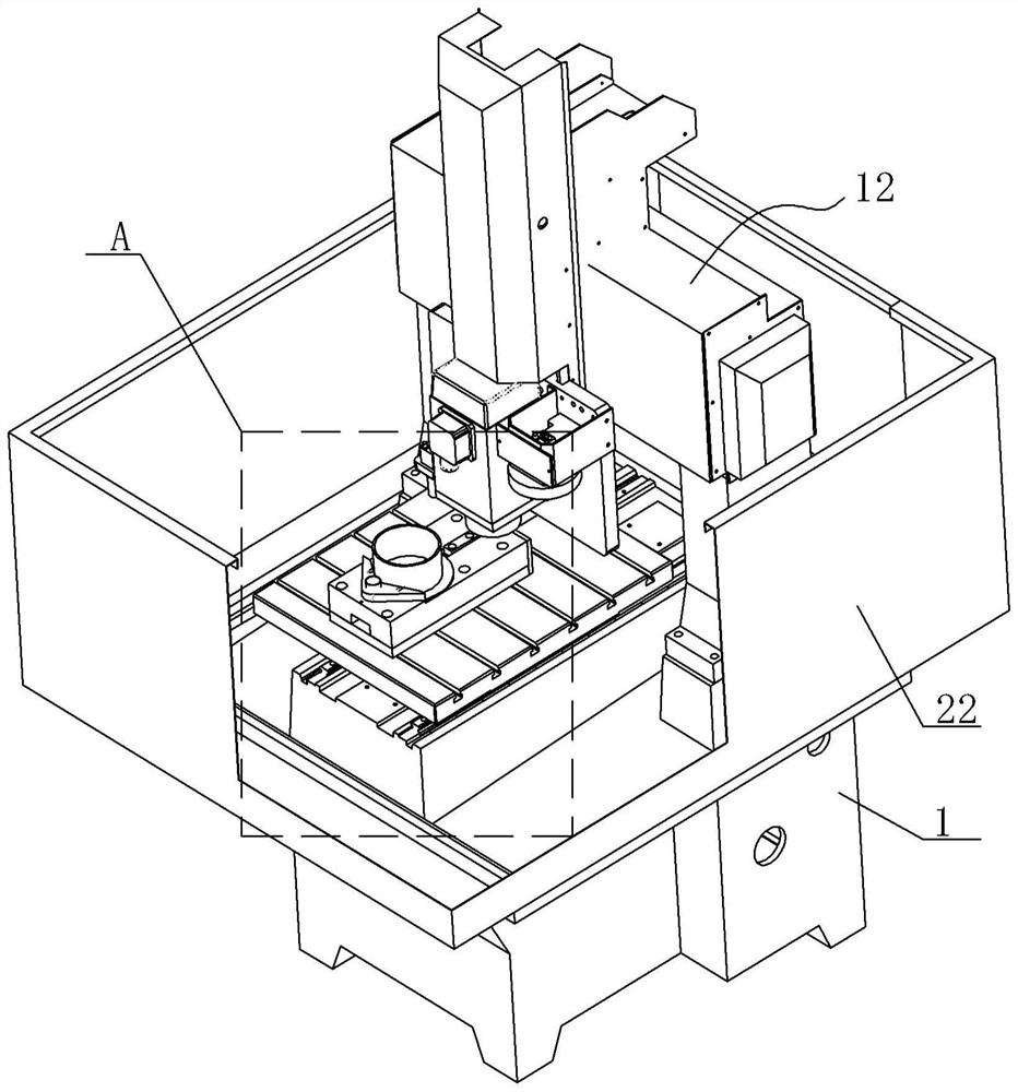
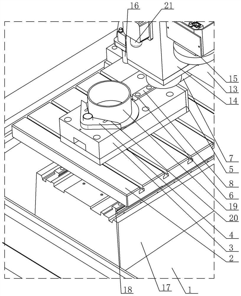
[0021] Flexible chamfering machine for disc parts based on machine vision, see Figure 1-Figure 3 : It includes a base 1, a processing platform 2 is provided in the central area of ​​the upper surface of the base 1 in the width direction, a backlight light source module 3 is fixedly mounted on the front of the upper surface of the processing platform 2, and a front end of the upper surface of the backlight light source module 3 is fixed There is a tool positioning plate 4, a cylinder mounting plate 5 is fixed on the rear surface of the backlight light source module 3, a concave guide groove 6 is provided at the center of the width direction of the rear section of the backlight light source module 3, and the compression cylinder 7 is fixed on The cylinder mounting plate 5, the piston pressing head 8 of the pressing cylinder 7 is placed in the recessed guide groove 6. The piston pressing head 8 protrudes on the upper surface of the backlight light source module 3, and the width di...


PUM


Abstract

The invention provides a disc part flexible chamfering machine based on machine vision. According to the disc part flexible chamfering machine based on machine vision, after a workpiece is placed in acorresponding area of a workbench, the whole equipment automatically finishes recognition and positioning of an end surface hole of the workpiece, and then finishes chamfering of the hole; and the chamfering is fast and convenient, the labor cost is saved for enterprises, and the product quality is improved. The disc part flexible chamfering machine based on machine vision comprises a base; a machining platform is arranged in a central area, in the width direction, of the upper surface of the base; a backlight source module is fixedly mounted at the front part of the upper surface of the machining platform; a tooling locating plate is fixedly arranged at the front end of the upper surface of the backlight source module; a cylinder mounting plate is fixedly arranged on the rear end surfaceof the backlight source module; a concave guide groove is formed in the central position, in the width direction, of a rear section area of the backlight source module; a pressing cylinder is fixedlymounted on the cylinder mounting plate; a piston pressing head of the pressing cylinder is placed in the concave guide groove; and one part of the piston pressing head is convex upwards on the uppersurface of the backlight source module.

Description

Technical field [0001] The invention relates to the technical field of chamfering machine structures, in particular to a flexible chamfering machine for disc parts based on machine vision. Background technique [0002] Disc parts (such as flexible wheels, steel wheels, cams and cross bearings) play a vital role in industrial robots and other equipment, and their production and processing procedures are also very strict. Because there are many holes on the surface, and the size of each hole is not exactly the same, this adds a lot of difficulties to production. The traditional artificial hole chamfering method is highly dependent on people, and the size of the chamfer cannot be quantitatively controlled. At the same time, there is a certain degree of danger in the operation process. The traditional chamfering machine has obvious defects and insufficient flexibility. It requires accurate and consistent positioning of the workpiece. In addition, the tooling, cutting tool, and proce...

Claims


Application Information

Patent Timeline
IPC IPC(8): B23Q3/08B23Q17/20B23Q17/22B23Q15/00
CPCB23Q3/08B23Q17/20B23Q17/22B23Q15/00
Inventor 赵洪锋
Owner 苏州麻雀智能科技有限公司
Learn More