
A split mold

A split type, mold technology, applied in the direction of molds, mold auxiliary parts, manufacturing tools, etc., can solve the problems of ceramic defects, gypsum entering the gap, etc., and achieve the effect of improving the appearance

Active Publication Date: 2021-06-22
山东鹤鹏技术有限公司
View PDF0 Cites 0 Cited by
  • Summary
  • Abstract
  • Description
  • Claims
  • Application Information

AI Technical Summary

Problems solved by technology

[0003] Based on the above inventors' discovery, the existing split mold mainly has the following disadvantages. For example, when ceramics are processed and formed, it is necessary to put gypsum into two pressing modules, and then clamp the gypsum to obtain molding. ceramics, and the two pressing modules are composed of a combination, so there will be a certain gap between the pressing modules, which will cause gypsum to enter the gap when pressing the mold, resulting in flaws in the molded ceramics.

Method used


Image

  • A split mold
  • A split mold
  • A split mold

Examples


Embodiment 1

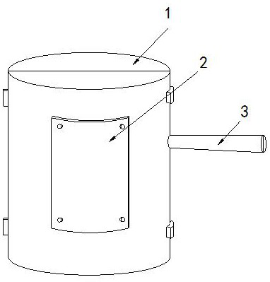
[0026] Example 1: Please refer to Figure 1-Figure 5 , the specific embodiments of the present invention are as follows:

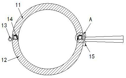
[0027] Its structure includes a main body 1, a model plate 2, and a handle 3. The side end of the main body 1 is provided with a model plate 2, and the handle 3 is installed in the middle of the side end of the main body 1. The main body 1 includes an upper module 11, a lower module 12, rotating shaft 13, rolling device 14, closing switch 15, the other side of described upper module 11 is provided with lower module 12, and described rotating shaft 13 connects upper module 11 and lower module 12, and described rolling device 14 It is arranged in the upper module 11 and movably cooperates with the lower module 12 .

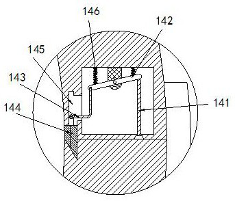
[0028] The flattening device 14 includes a push rod 141, a balance bar 142, a push rod 143, a smoothing block 144, a slide groove 145, and a first spring 146. Movably fit, the balance bar 142 is engaged on the top of the rolling device 14, the...

Embodiment 2

[0032] Example 2: Please refer to Figure 6-Figure 8 , the specific embodiments of the present invention are as follows:

[0033] The smoothing block 144 includes a rolling groove b1, a roller b2, a movable rod b3, an elastic piece b4, and a smoothing body b5. The rolling groove b1 is arranged at the side end of the smoothing block 144. , and installed in the rolling groove b1, the movable rod b3 is provided with two, and installed crosswise in the roller b2, the elastic sheet b4 connects the two movable rods b3, and the smoothing body b5 is embedded in At the end of the movable rod b3, the included angle between the smoothing blocks 144 is 120 degrees, which is beneficial to smoothing the protruding gypsum.

[0034] The smoothing body b5 includes a fixed block b51, a mud collecting groove b52, a groove b53, and a plastering block b54. There are two fixed blocks b51, which are located at the bottom of the smoothing body b5 and move with the movable rod b3 Cooperate, the said...


PUM


Abstract

The invention discloses a split mold, the structure of which comprises a main body, a model plate, and a handle. The side end of the main body is provided with a model plate, and the handle is installed in the middle of the side ends of the main body. The main body includes an upper module, a lower module, a rotating shaft, a flattened device, closing switch, rolling device includes push rod, balance bar, ejector rod, smoothing block, sliding groove, first spring, balance bar includes rotating hole, engaging groove, pushing block, balancing device, and balancing device includes supporting block , a rotating rod, a second spring, and a connecting rod. When the upper module and the lower module are closed in the present invention, the push rod will push up the balance rod, so that the other end of the balance rod will drive the push rod to slide downward, so that the troweling block is The gypsum that has entered the gaps is squeezed, smoothing it and avoiding flaws in the ceramic.

Description

technical field [0001] The invention relates to the field of molds, in particular to a split mold. Background technique [0002] Molds, various molds and tools used in industrial production for injection molding, blow molding, extrusion, die-casting or forging forming, smelting, stamping, etc. to obtain the required products; in short, molds are tools used to make shaped objects , this tool is composed of various modules, and different molds are composed of different modules; it mainly realizes the processing of the shape of the object through the change of the physical state of the formed material. [0003] Based on the above inventors' discovery, the existing split mold mainly has the following disadvantages. For example, when ceramics are processed and formed, it is necessary to put gypsum into two pressing modules, and then clamp the gypsum to obtain molding. Ceramics, and the two pressing modules are composed of a combination, so there will be a certain gap between the...

Claims


Application Information

Patent Timeline
Patent Type & Authority Patents(China)
IPC IPC(8): B28B7/00B28B1/29
CPCB28B1/29B28B7/0002B28B7/0029B28B7/0097
Inventor 林洁雄
Owner 山东鹤鹏技术有限公司
Learn More